Latch pin for use in valve lifter and valve lifter
- Summary
- Abstract
- Description
- Claims
- Application Information
AI Technical Summary
Benefits of technology
Problems solved by technology
Method used
Image
Examples
Embodiment Construction
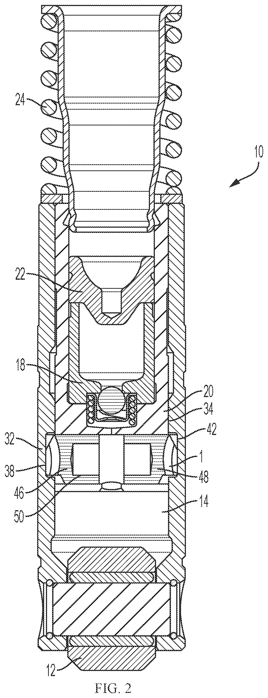
[0027]FIG. 2 shows an embodiment of a hydraulic deactivation lifter (HDL) 10 of the present invention. The HDL 10 includes a roller 12, a lifter body 14, a deactivation pin assembly (latch pin assembly) 1, a plunger assembly 18, a pin housing 20, a pushrod seat assembly 22, and a spring 24.
[0028]The deactivation pin assembly 1 is received within the pin housing 20, which is in turn arranged inside the cylindrical hollow lifter body 14. The deactivation pin assembly 1 is normally placed in an engagement position where it engages with the lifter body 14, thereby transferring the axial reciprocating movement of the lifter body 14 to the pin housing 20 and further to the plunger assembly 18 and pushrod seat assembly 22. In this engagement position, the axial reciprocating movement of HDL 10 opens and closes a valve of the engine.
[0029]When the deactivation pin assembly 1 disengages from the lifter body 14, the lifter body 14 is decoupled from pin housing 20 accordingly and, in turn, the...
PUM
 Abstract
Description
Claims
Application Information
 - R&D
- Intellectual Property
- Life Sciences
- Materials
- Tech Scout
- Unparalleled Data Quality
- Higher Quality Content
- 60% Fewer Hallucinations
Browse by: Latest US Patents, China's latest patents, Technical Efficacy Thesaurus, Application Domain, Technology Topic, Popular Technical Reports.
© 2025 PatSnap. All rights reserved.Legal|Privacy policy|Modern Slavery Act Transparency Statement|Sitemap|About US| Contact US: help@patsnap.com


