Automatic analysis device

a technology of automatic analysis and analysis results, applied in the direction of material analysis, instruments, etc., can solve the problems of affecting the next analysis result, and achieve the effect of high accuracy and reliable analysis

Pending Publication Date: 2021-03-18
HITACHI HIGH-TECH CORP
View PDF9 Cites 0 Cited by
  • Summary
  • Abstract
  • Description
  • Claims
  • Application Information

AI Technical Summary

Benefits of technology

[0009]According to the above aspect, the liquid is caused to remain so that the bottom surface of the reactor vessel is not exposed due to the rough suction nozzle for suctioning the liquid such as the washing liquid before suctioning with the washing tip, such that a remaining liquid after washing can be reduced regardless of a position of the washing tip. Therefore, affection on the analysis due to thinning of the sample and the reagent due to the remaining liquid of the washing liquid is reduced, and it is possible to contribute to realization of a highly accurate and reliable analysis.

Problems solved by technology

At this time, if the remaining liquid remains in the reactor vessel after the washing, the next analysis result is affected.

Method used


Image

  • Automatic analysis device
  • Automatic analysis device
  • Automatic analysis device

Examples


embodiment 1

[0023]

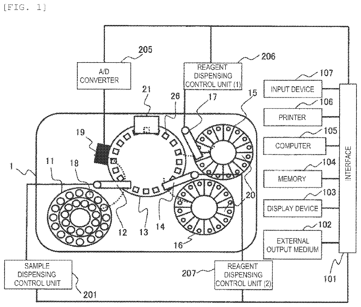
[0024]FIG. 1 is a diagram showing a basic configuration of an automatic analysis device according to an embodiment. Here, as an aspect of the automatic analysis device, an example of a turntable type biochemical analysis device will be described.

[0025]As shown in this diagram, the automatic analysis device 1 includes a reaction disk 13, a sample disk 11, a first reagent disk 15, a second reagent disk 16, a photometer 19, and a washing mechanism 21 which are disposed on a housing body.

[0026]The reaction disk 13 is a disk-shaped unit which is rotatable in a clockwise direction and a counterclockwise direction, and a plurality of reactor vessels 26 can be arranged on a circumference thereof.

[0027]The sample disk 11 is a disk-shaped unit which is rotatable in the clockwise direction and the counterclockwise direction, and a plurality of sample vessels 18 containing biological samples such as standard samples and test samples can be arranged on the circumference thereof.

[0028]The f...

embodiment 2

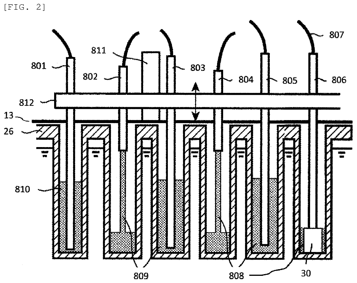
[0055]Next, another shape of the washing tip 30 of the automatic analysis device 1 according to the present embodiment will be described. In Embodiment 1 described above, a case where an appearance of the washing tip 30 is formed by a simple rectangular parallelepiped has been shown and described. Here, a rectangular parallelepiped 41 formed with a maximum width on an upper portion of the washing tip 30, a rectangular parallelepiped 42 formed with a smaller width than that of the upper portion on a lower portion of the washing tip 30, and a rectangular parallelepiped 43 formed with a minimum width between the upper portion and the lower portion are stacked (hereinafter, sometimes referred to as an I shape), and the above will be described with reference to FIG. 10. FIG. 10 is a conceptual diagram showing a state at the time of suction with an I-shaped washing tip 40 according to an embodiment (Embodiment 2).

[0056]In an example shown in this diagram, as described above, the I-shaped ...


PUM

PropertyMeasurementUnit
suction speedaaaaaaaaaa
cross-sectional areaaaaaaaaaaa
timeaaaaaaaaaa

Abstract

When washing the inside of a reactor vessel which is used repeatedly, a rough suction is performed before suctioning with a washing tip; however, unwanted washing liquid may remain that may affect analysis results. The present invention provides an automatic analysis device for analyzing a sample using light, in which the automatic analysis device is characterized in that: a washing mechanism comprises a washing liquid supply nozzle that supplies washing liquid to a reactor vessel after analysis, a washing liquid suction nozzle that suctions the supplied washing liquid, a washing tip provided to the bottom end of the washing liquid suction nozzle, and a rough suction nozzle that suctions, in advance, a liquid within the reactor vessel before suctioning with the washing tip; and after the rough suction, liquid is caused to remain so that the bottom surface of the reactor vessel is not exposed.

Description

TECHNICAL FIELD[0001]The present invention relates to an automatic analysis device for analyzing a biological sample such as blood and urine, and particularly relates to an automatic analysis device which includes a washing mechanism for washing a reactor vessel.BACKGROUND ART[0002]An automatic analysis device is a device which qualitatively analyzes a biological sample (hereinafter, sometimes referred to as a sample) such as blood or urine. The sample and a reagent are reacted in a reactor vessel to analyze a component of a measured object in the sample. The reactor vessel is formed of a material such as plastic or glass, and in particular, in a device which analyzes items such as a biochemical analysis, the reactor vessel used for one measurement is commonly washed and used repeatedly. A washing operation of the reactor vessel includes: moving the reactor vessel to a predetermined washing position, repeatedly injecting and suctioning a washing liquid such as a detergent or a washi...

Claims


Application Information

Patent Timeline
Patent Type & Authority Applications(United States)
IPC IPC(8): G01N35/02
CPCG01N35/02G01N2035/00396G01N2035/0437G01N35/04
Inventor SHIOYA, KEIAKASE, HIROKIKONISHI, REISAKAGUCHI, MASAAKI
Owner HITACHI HIGH-TECH CORP
Why Eureka
Try Eureka