
A low-voltage differential signal interface matching resistance automatic detection device and method

A low-voltage differential signal, automatic detection technology, applied in the direction of measuring resistance/reactance/impedance, parts of electrical measuring instruments, measuring devices, etc., can solve problems such as efficiency of bad analysis, time-consuming and labor-intensive, affecting products, etc., to improve detection Efficiency and product failure analysis capabilities, accurate and reliable analysis, and strong practicability

Active Publication Date: 2017-03-01
BOE TECH GRP CO LTD +1
View PDF8 Cites 0 Cited by
  • Summary
  • Abstract
  • Description
  • Claims
  • Application Information

AI Technical Summary

Problems solved by technology

[0005] During the production process of LCD modules and panels, the low-voltage differential signal interface matching resistors in the drive circuit boards sometimes fall off or are missing, resulting in poor image output of LCD modules and panels.
Due to the large number of components such as resistors on the drive circuit board, it is difficult to find missing matching resistors in a timely and effective manner, which affects the efficiency of product failure analysis
[0006] Moreover, in the case of low-voltage differential signal interface matching resistance solder joints, it is almost impossible to find the abnormality of the matching resistance in appearance, and can only measure each matching resistance with an electronic multimeter manually. It is difficult to find the matching resistance, and it is time-consuming and laborious. , which increases the difficulty of bad product analysis

Method used


Image

  • A low-voltage differential signal interface matching resistance automatic detection device and method
  • A low-voltage differential signal interface matching resistance automatic detection device and method
  • A low-voltage differential signal interface matching resistance automatic detection device and method

Examples


Embodiment Construction

[0053] In order to make the purpose, technical solutions and advantages of the embodiments of the present invention more clear, the following will clearly and completely describe the technical solutions of the embodiments of the present invention in conjunction with the drawings of the embodiments of the present invention. Apparently, the described embodiments are some, not all, embodiments of the present invention. All other embodiments obtained by those skilled in the art based on the described embodiments of the present invention belong to the protection scope of the present invention.

[0054] Unless otherwise defined, the technical terms or scientific terms used herein shall have the usual meanings understood by those skilled in the art to which the present invention belongs. "First", "second" and similar words used in the patent application specification and claims of the present invention do not indicate any order, quantity or importance, but are only used to distinguis...


PUM


Abstract

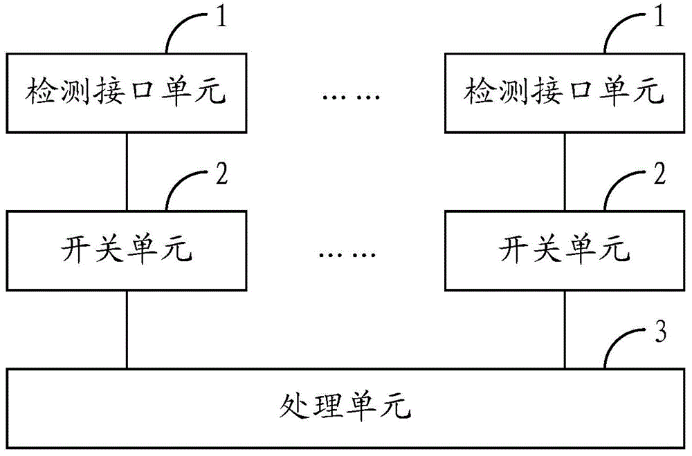
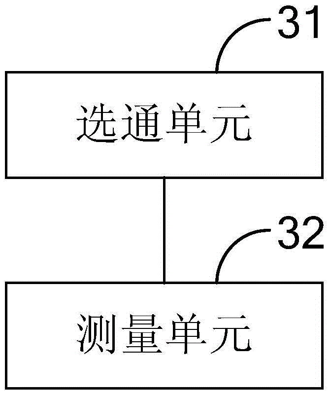
The invention provides a low-voltage differential signal interface matching resistance automatic detection device and method. By setting a plurality of detection interface units including two terminals for connecting with both ends of the low-voltage differential signal interface matching resistance; At least one switch unit between the corresponding detection interface units, the switch unit is set correspondingly with the detection interface unit; the processing unit is used to control the switch unit to be in an on state, so that the detection interface unit corresponding to the switch unit in the on state and the processing unit The unit forms a detection loop, and uses the detection loop to measure the matching resistance of the low-voltage differential signal interface connected to the detection interface unit corresponding to the switch unit in the conducting state. Therefore, the detection of the matching resistance of the low-voltage differential signal interface can be automatically realized, and the analysis is accurate and reliable, the operation is convenient, and the practicability is strong, which significantly improves the detection efficiency of the matching resistance and the ability to analyze product defects.

Description

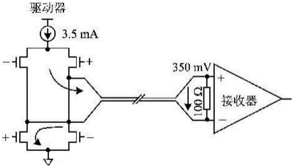
technical field [0001] The invention relates to the field of display technology, and specifically relates to a low-voltage differential signal interface matching resistance automatic detection device and method. Background technique [0002] Currently, a liquid crystal module (LCM) and a panel (Open Cell) mainly use a low voltage differential signal (LVDS: Low Voltage Differential Signal) to transmit display signals. [0003] Low-voltage differential signals are generally transmitted by more than 4 pairs of differential signal lines, each pair of differential signal lines has 2 wires, and between the 2 wires, impedance matching must be performed by a matching resistor of 100Ω. [0004] The most basic LVDS devices are LVDS drivers and receivers, as shown in the attached figure 1 As shown, the low-voltage differential signal driver consists of a current source that drives a low-voltage differential signal line pair. The current is usually 3.5mA. The low-voltage differential s...

Claims


Application Information

Patent Timeline
Patent Type & Authority Patents(China)
IPC IPC(8): G01R27/14
CPCG09G3/006G09G5/006G09G2370/14G09G2370/22G01R1/0416G01R27/02G01R27/14
Inventor 褚路路张纪王天超
Owner BOE TECH GRP CO LTD
Learn More