
Fault cause determination method and device, equipment and storage medium

A technology for failure causes and determination methods, applied in biological neural network models, other database retrieval, resources, etc., can solve problems such as low efficiency, lack of clear connections, and inconvenient intelligent decision-making, and achieve accurate and reliable analysis.

Active Publication Date: 2021-11-16
SHANGHAI AIRCRAFT MFG
View PDF7 Cites 0 Cited by
  • Summary
  • Abstract
  • Description
  • Claims
  • Application Information

AI Technical Summary

Problems solved by technology

In the actual production process, due to the heavy production tasks and high quality requirements, the complexity of the production process environment is greatly increased, and it is more likely to cause failures
[0003] The cause of failure events is traditionally judged by staff based on human experience, but for traditional manufacturing companies, the workshop production process is complex and unpredictable, and the cause of failure may be equipment, tooling, personnel It is obviously inefficient to judge the cause of the fault simply based on the experience of the staff, and it is impossible to effectively avoid the occurrence of similar faults.
In addition, in the current fault analysis, there is no clear connection between the generated faults and equipment, tooling, personnel, materials, processes, environment, etc., and they are scattered in the equipment or human brain, resulting in fragmented and independent distribution of existing industrial knowledge characteristics, and many rely on the experience of technicians, which brings inconvenience to industrial intelligent decision-making

Method used


Image

  • Fault cause determination method and device, equipment and storage medium
  • Fault cause determination method and device, equipment and storage medium
  • Fault cause determination method and device, equipment and storage medium

Examples


Embodiment 1

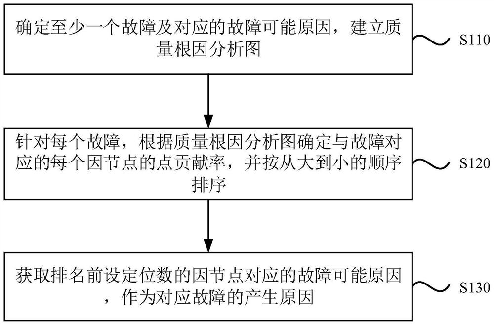
[0060] figure 1 It is a flow chart of a fault cause determination method provided by Embodiment 1 of the present invention. This embodiment is applicable to the situation of analyzing and determining the cause of a fault in an industrial process. This method can be executed by a fault cause determination device. The device can be composed of hardware and / or software, and can generally be integrated into a device with a function of determining the cause of a fault, and the device can be an electronic device such as a server or a server cluster.

[0061] Such as figure 1 As shown, it specifically includes the following steps:

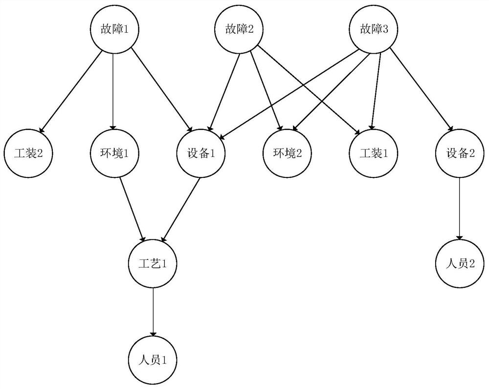
[0062] Step 110, determine at least one fault and the corresponding possible cause of the fault, and establish a quality root cause analysis diagram.

[0063] Among them, the fault can be an abnormal event that affects the production quality or production efficiency in the industrial production process. For traditional manufacturing enterprises, the wor...

Embodiment 2

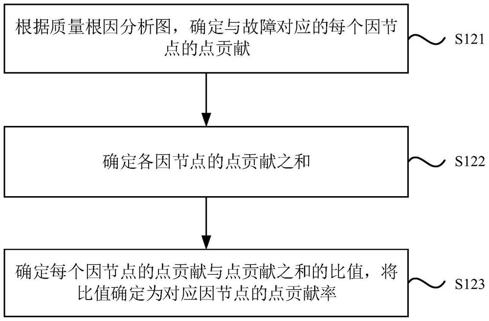
[0080] image 3 It is a flowchart of a method for determining a point contribution rate provided by Embodiment 2 of the present invention. This embodiment is applicable to the case of determining the contribution rate of each fault corresponding to a root-cause node in a quality root cause analysis graph.

[0081] Such as image 3 As shown, it specifically includes the following steps:

[0082] Step 121 , according to the quality root cause analysis diagram, determine the point contribution of each causal node corresponding to the fault.

[0083] In this embodiment, each fault may correspond to multiple causal nodes, and for each fault, the point contribution of each causal node may be calculated.

[0084] Optionally, according to the quality root cause analysis diagram, the method of determining the point contribution of each causal node corresponding to the fault may be: extracting the first-degree node, second-degree node and third-degree node corresponding to the fault i...

Embodiment 3

[0094] Figure 4 It is a structural schematic diagram of a device for determining the cause of a fault provided by Embodiment 3 of the present invention. Such as Figure 4 As shown, the device includes: a quality root cause analysis diagram establishment module 210 , a point contribution rate sorting module 220 , and a cause determination module 230 .

[0095] The quality root cause analysis diagram establishment module 210 is configured to determine at least one fault and the corresponding possible cause of the failure, and establish a quality root cause analysis diagram.

[0096] Optionally, the quality root cause analysis diagram establishment module 210 is also used for:

[0097] Obtain a fault file containing fault information, parse the fault file, and obtain at least one fault; determine a possible cause of the fault based on at least one fault and combined with production process information.

[0098] Optionally, the quality root cause analysis diagram establishment...


PUM


Abstract

The embodiment of the invention discloses a fault cause determination method which comprises the following steps: determining at least one fault and a corresponding fault possible cause, and establishing a quality root cause analysis chart; cause nodes in the quality root cause analysis graph are in one-to-one correspondence with possible causes of the fault; aiming at each fault, determining the point contribution rate of each cause node corresponding to the fault according to the quality root cause analysis graph, and sorting according to a sequence from large to small; and obtaining the fault possible cause corresponding to the cause node with the set digit before ranking as the generation cause of the corresponding fault. According to the fault cause determination method provided by the embodiment of the invention, the quality root cause analysis graph is established, the graph database algorithm is combined, and the point contribution rate of the cause nodes is calculated and sorted, so that the fault cause which has the greatest influence on the fault is determined, the digitalization of the workshop production and manufacturing process is realized, the industrial process and the complex relationship can be clearly described, an industrial neural network is formed, and the fault generation cause is analyzed accurately and reliably.

Description

technical field [0001] The present invention relates to the technical field of fault diagnosis, in particular to a fault cause determination method, device, equipment and storage medium. Background technique [0002] In the traditional industrial manufacturing field, the management of the workshop includes the maintenance of normal conditions and the handling of faults. The occurrence of such faults and the delayed resolution of faults will not only increase operating costs, but also seriously affect the work of employees. Efficiency and long-term development of enterprises. Therefore, the handling of fault events and the analysis of their causes are very important. In the actual production process, due to the heavy production tasks and high quality requirements, the complexity of the production process environment is greatly increased, and it is more likely to cause failures. [0003] The cause of failure events is traditionally judged by staff based on human experience, ...

Claims


Application Information

Patent Timeline
Patent Type & Authority Applications(China)
IPC IPC(8): G06F16/903G06F16/901G06F16/9038G06N3/02G06Q10/06G06Q50/04
CPCG06F16/90335G06F16/9024G06F16/9038G06N3/02G06Q10/06395G06Q50/04Y02P90/30
Inventor 廉以佳谢晨薛丹杨帆黄奕刘丰维
Owner SHANGHAI AIRCRAFT MFG
Learn More