
Anywhere damper

a damper and anywhere technology, applied in the direction of shock absorbers, springs/dampers design characteristics, vibration dampers, etc., can solve the problems of no protection of the system, damage to the cable itself or the components that are attached, and vibration in the conductor or non-conductor cabl

Active Publication Date: 2021-04-08
AFL COMM LLC
View PDF0 Cites 2 Cited by
  • Summary
  • Abstract
  • Description
  • Claims
  • Application Information

AI Technical Summary

Benefits of technology

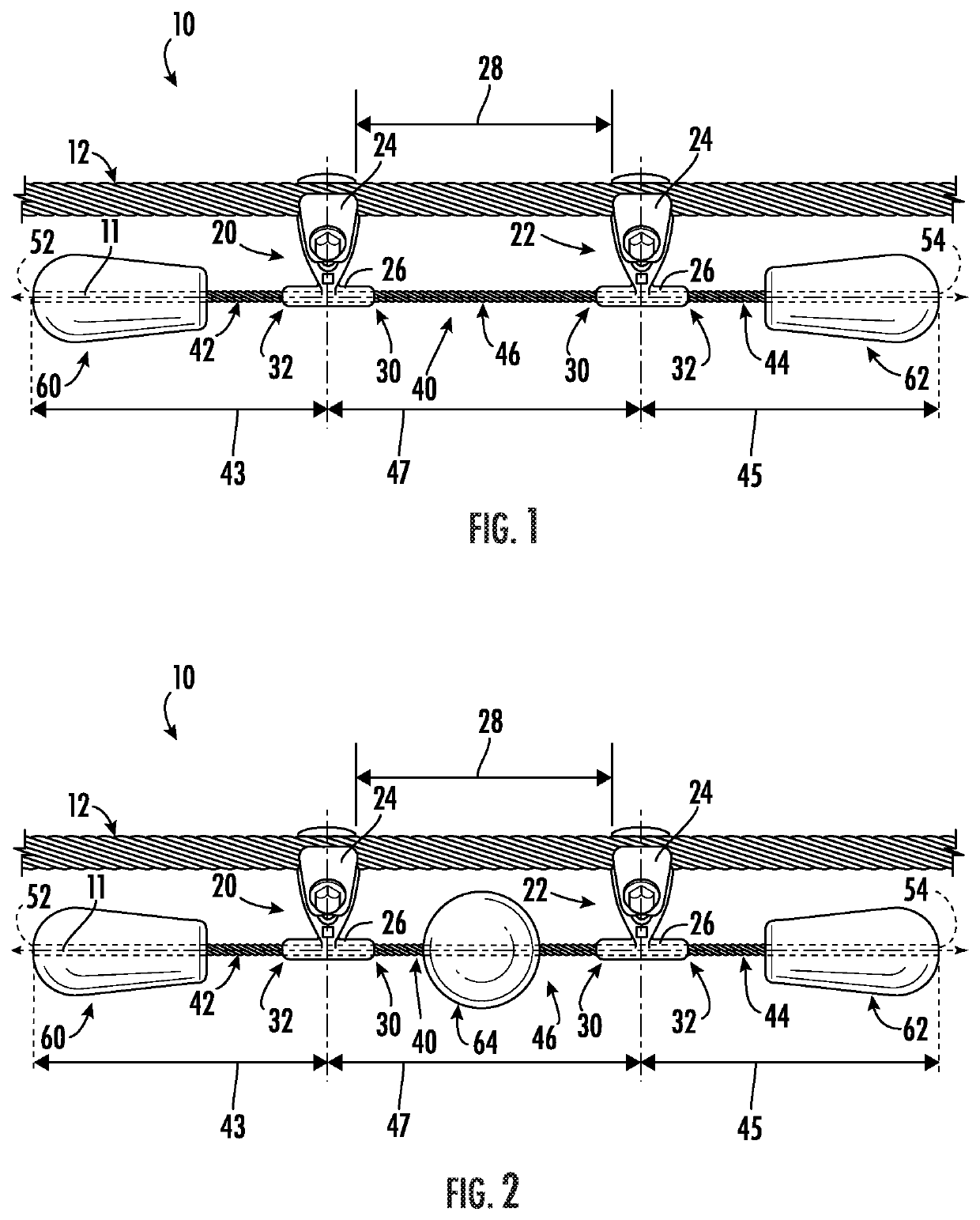
The present patent describes a Stockbridge damper that helps reduce vibrations caused by a rotating machine. The damper includes a first clamp and a second clamp, along with a wire strand which has a first end portion connected to the first clamp, a second end portion connected to the second clamp, and an intermediate portion between the first and second clamps. The damper also includes weights connected to the ends of the wire strand. The distance between the first and second clamps is less than 48 inches and the wire strand is positioned within a specific range. The technical effect of this design is that it provides a more effective reduction of vibrations due to its unique structure and the specific placement of the wire strand and weights.

Problems solved by technology

Aerial cable systems including but not limited to systems for the transmission / distribution of electricity, suspension bridge wires, and tower guy wires, are exposed to winds resulting in vibration in the conductor or non-conductor cable (collectively “cables”).
This vibration can lead to damage of the cable itself or components that are attached to it.
With this location / spacing requirement, there is potential for a damper to be placed on a node (point of no vibration) where the damper does not damp the cable and therefore provides no protection to the system.
These analyses take time on the planning side.

Method used


Image

  • Anywhere damper

Examples


Embodiment Construction

[0014]Reference now will be made in detail to embodiments of the present Stockbridge dampers, one or more examples of which are illustrated in the drawings. Each example is provided by way of explanation, rather than limitation of, the technology. In fact, it will be apparent to those skilled in the art that modifications and variations can be made in the present technology without departing from the scope or spirit of the claimed technology. For instance, features illustrated or described as part of one embodiment can be used with another embodiment to yield a still further embodiment. Thus, it is intended that the present disclosure covers such modifications and variations as come within the scope of the appended claims and their equivalents.

[0015]The detailed description uses numerical and letter designations to refer to features in the drawings. Like or similar designations in the drawings and description have been used to refer to like or similar parts of the invention. As used...


PUM


Abstract

Stockbridge dampers are provided. A Stockbridge damper includes a first clamp, and a second clamp spaced along a longitudinal axis from the first clamp, wherein a distance is defined along the longitudinal axis between the first clamp and the second clamp. A Stockbridge damper further includes a wire strand extending generally along the longitudinal axis through and between the first clamp and the second clamp, the wire strand including a first end portion extending from a distal side of the first clamp, a second end portion extending from a distal side of the second clamp, and an intermediate portion extending between proximal sides of the first and second clamps. A Stockbridge damper further includes a first weight connected to the first end portion of the wire strand, and a second weight connected to the second end portion of the wire strand.

Description

PRIORITY CLAIM[0001]The present application claims priority to U.S. Provisional Patent Application Ser. No. 62 / 912,367, filed on Oct. 8, 2019, the disclosure of which is incorporated by reference herein in its entirety.FIELD[0002]The present disclosure relates generally to Stockbridge dampers, and more particularly to improved Stockbridge dampers which may provide improved performance and / or ease of placement.BACKGROUND[0003]Aerial cable systems including but not limited to systems for the transmission / distribution of electricity, suspension bridge wires, and tower guy wires, are exposed to winds resulting in vibration in the conductor or non-conductor cable (collectively “cables”). This vibration can lead to damage of the cable itself or components that are attached to it. To mitigate this vibration, various forms of dampers can be used, with the most common being the Stockbridge damper (symmetrical or asymmetrical types). These dampers are placed at specific locations and spacing ...

Claims


Application Information

Patent Timeline
Patent Type & Authority Applications(United States)
IPC IPC(8): F16F7/116
CPCF16F7/116H02G7/14F16F2224/0208F16F2230/0005F16F2222/08
Inventor KRANZ, STEVENPRICE, III, CHARLES MONROEAGNEW, MOREY ROBERT SAMUEL
Owner AFL COMM LLC
Learn More