Crash impact attenuator systems and methods

a technology of impact attenuators and attenuators, which is applied in roadway safety arrangements, roadways, construction, etc., can solve the problems of uneven size of holes, and achieve the effect of increasing the attenuation of impact for

Inactive Publication Date: 2021-04-15
TRAFFIX DEVICES INC
View PDF0 Cites 6 Cited by
  • Summary
  • Abstract
  • Description
  • Claims
  • Application Information

AI Technical Summary

Benefits of technology

[0006]The present invention comprises, in one exemplary aspect, a crash attenuator system for deployment in front of a fixed structure, such as a bridge abutment. The system comprises a rail extending along a length of the crash attenuator system, a plurality of diaphragms initially disposed in spaced relation along the length of the rail, each of the plurality of diaphragms having a base end adapted to be movably engaged with the rail, so that when a front end of the crash attenuator system receives an impact force from an errant vehicle, a first one of the plurality of diaphragms moves rearwardly along the rail and impacts a second one of the plurality of diaphragms so that both the first and second ones of the plurality of diaphragms move further rearwardly along the rail, this process continuing with additional ones of the plurality of diaphragms until the impact forces have been fully attenuated. The system further comprises a tearing member on the crash attenuator system which is adapted to engage material forming a tearable member of the crash attenuator system, the tearing member and the tearable member being relatively movable when an impact force strikes the crash attenuator system so that the tearing member tears the tearable member, thereby increasing attenuation of the impact force.
[0014]In still another aspect of the invention, there is provided a crash attenuator system for deployment in front of a fixed structure, the system comprising a base portion having a first outer rail extending along a length of the base portion, a second outer rail spaced from the first outer rail and also extending along a length of the base portion, and a plurality of spaced cross-members extending across a width of the base portion and joining the first outer rail to the second outer rail. An upper attenuator portion comprises a plurality of diaphragms initially disposed in spaced relation along the length of the base portion. Each of the plurality of diaphragms has a base end adapted to be movably engaged with each of the first outer rail and the second outer rail, so that when a front end of the upper attenuator portion receives an impact force from an errant vehicle, a first one of the plurality of diaphragms moves rearwardly along the first and second outer rails and impacts a second one of the plurality of diaphragms, so that both the first and second ones of the plurality of diaphragms move further rearwardly along the first and second outer rails, this process continuing with additional ones of the plurality of diaphragms until the impact forces have been fully attenuated. A tearing member is disposed on the upper attenuator portion, which is adapted to engage material forming a tearable member of the upper attenuator portion, the tearing member and the tearable member being relatively movable when an impact force strikes the crash attenuator system so that the tearing member tears the tearable member, thereby increasing attenuation of the impact force.

Problems solved by technology

In some circumstances, the plurality of holes are not uniform in size, respective to one another.

Method used


Image

  • Crash impact attenuator systems and methods
  • Crash impact attenuator systems and methods
  • Crash impact attenuator systems and methods

Examples


Embodiment Construction

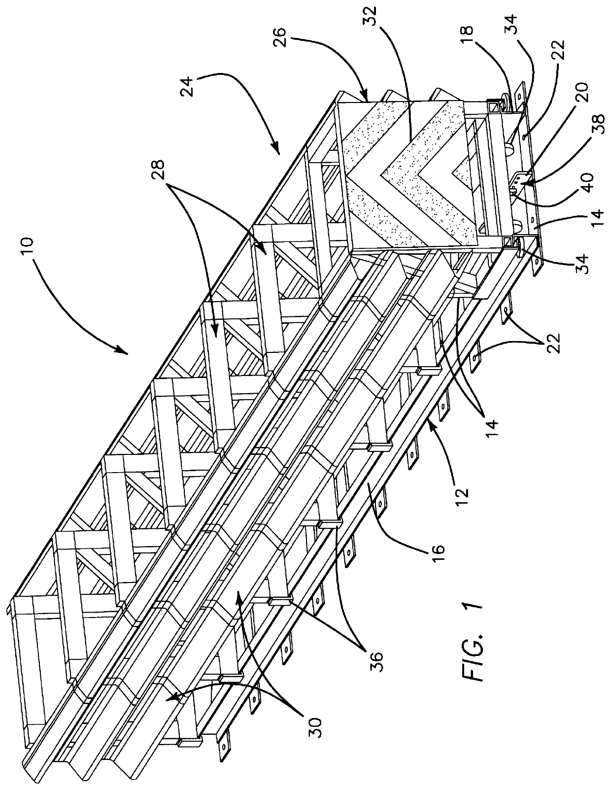
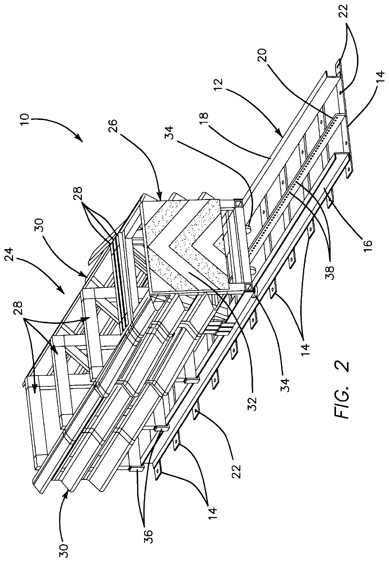
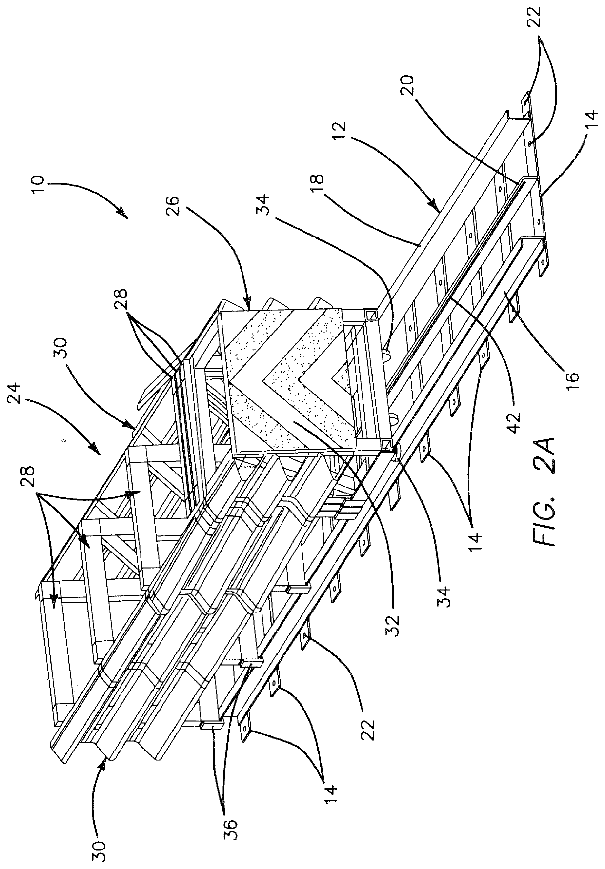
[0024]Referring now more particularly to the drawings, FIGS. 1-4 illustrate an exemplary embodiment of a fixed crash impact attenuator system 10 of the type discussed above, wherein the design is sacrificial, in that it is intended for a single impact only, after which it is replaced. Thus, it is designed to be relatively inexpensive and simple in design and construction, yet highly effective in protecting the occupants of vehicles striking the attenuator.

[0025]Design considerations for the system 10 are that it meets U.S. federal TL (Test Level)-3 crash attenuation specifications, that it is narrow in profile, bi-directional capable, MASH (Manual for Assessing Safety Hardware) compliant, inexpensive, and free-standing (does not need to butt to rigid object, although it can, of course). The system is of a simple design and easy to manufacture (materials are standard sizes and shapes and fender panels are standard Thrie Beam-based), easy to assemble, and ships as a complete assembly....


PUM


Abstract

A crash attenuator system for deployment in front of a fixed structure includes a rail extending along a length of the crash attenuator system and a plurality of diaphragms initially disposed in spaced relation along the length of the rail. Each of the plurality of diaphragms moves along the rail, so that when a front end of the crash attenuator system receives an impact force from a vehicle, a first one of the diaphragms moves rearwardly along the rail and impacts a second one of the diaphragms so that both the first and second diaphragms move further rearwardly along the rail, this process continuing with additional ones of the diaphragms until the impact forces have been fully attenuated. A tearing member on the crash attenuator system engages material forming a tearable member of the crash attenuator system, the tearing member tearing material forming the tearable member to increase attenuation of the impact force.

Description

[0001]This application claims the benefit under 35 U.S.C. 119(e) of the filing date of U.S. Provisional Application Ser. No. 62 / 915,592, entitled Crash Impact Attenuator Systems and Methods, filed on Oct. 15, 2019, and of U.S. Provisional Application Ser. No. 63 / 054,911, entitled Crash Impact Attenuator Systems and Methods, filed on Jul. 22, 2020. Both of the foregoing applications are commonly assigned with the present application, and are each expressly incorporated herein by reference, in their entirety.BACKGROUND OF THE INVENTION[0002]The present invention relates generally to crash impact attenuators, and more particularly to motor vehicle and highway barrier crash impact attenuators comprising fixed systems protecting leading edges of abutments and other fixed roadside hazards.[0003]Vehicular accidents on the highway are a major worldwide problem and are undoubtedly one of the largest causes of economic and human loss and suffering inflicted on the developed world today. In an...

Claims


Application Information

Patent Timeline
Patent Type & Authority Applications(United States)
IPC IPC(8): E01F15/14E01F15/04
CPCE01F15/146E01F15/0423
Inventor MAUS, GEOFFREY B.ALMANZA, FELIPEKULP, JACK H.
Owner TRAFFIX DEVICES INC
Why Eureka
Try Eureka