Linear compressor

Pending Publication Date: 2021-04-15
LG ELECTRONICS INC
View PDF6 Cites 0 Cited by
  • Summary
  • Abstract
  • Description
  • Claims
  • Application Information

AI Technical Summary

Benefits of technology

This patent is about a new type of linear compressor that has a discharge plenum inside a discharge cover, which helps to make sure that the refrigerant flows effectively into the gas hole. The compressor also has a discharge plenum that close contacts the discharge cover to prevent the frame from getting too hot from the refrigerant that is being compressed. Overall, this design helps to make sure that the bearing refrigerant flows at the shortest distance and doesn't get into the gas hole after flowing along the front surface of the frame.

Problems solved by technology

That is, there is a limitation in that the high-temperature refrigerant flows between the discharge unit and the frame to transfer heat to the frame.
(2) Also, as the heat is transferred from the frame to the piston and the cylinder, the suction refrigerant flowing inside the piston is overheated.
Thus, the suction refrigerant may increase in volume to deteriorate compression efficiency.
Thus, since the refrigerant has a very high temperature, there is a limitation of transferring relatively much heat to the suction refrigerant.
(3) Also, as the refrigerant discharged from the compressed space flows into the discharge cover, the discharge cover is overheated.
Particularly, there is a limitation in that the frame, the piston, and the cylinder are disposed to contact each other so that the heat of the frame is easily transferred to the piston and the cylinder by the conduction.

Method used


Image

  • Linear compressor
  • Linear compressor
  • Linear compressor

Examples


first embodiment

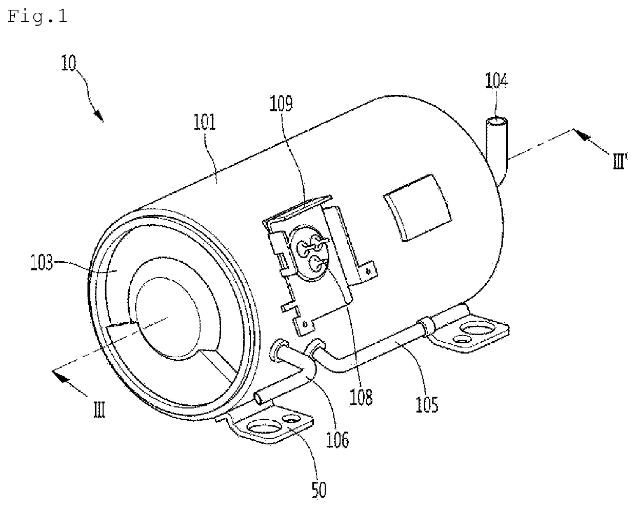
[0053]FIG. 1 is a view of a linear compressor according to a

[0054]Referring to FIG. 1, a linear compressor 10 according to an embodiment includes a shell 101 and shell covers 102 and 103 coupled to the shell 101. In a broad sense, each of the shell covers 102 and 103 may be understood as one component of the shell 101.

[0055]A leg 50 may be coupled to a lower portion of the shell 101. The leg 50 may be coupled to a base of a product in which the linear compressor 10 is installed. For example, the product may include a refrigerator, and the base may include a machine room base of the refrigerator. For another example, the product may include an outdoor unit of an air conditioner, and the base may include a base of the outdoor unit.

[0056]The shell 101 may have an approximately cylindrical shape and be disposed to lie in a horizontal direction or an axial direction. In FIG. 1, the shell 101 may extend in the horizontal direction and have a relatively low height in a radial direction. Th...

second embodiment

[0298]As illustrated in FIGS. 11 and 12, a bearing refrigerant passage X is provided to pass through a discharge plenum 292. Particularly, the bearing refrigerant passage X is provided to pass through a plenum guide surface 2928.

[0299]In detail, the discharge plenum 292 includes a plenum flange 2920 extending in a radial direction. Also, the plenum guide surface 2928 extends axially from the plenum flange 2920.

[0300]The plenum flange 2920 includes a bearing refrigerant hole 2323 defined to be penetrated. Also, the plenum guide surface 2928 extends from the plenum flange 2920 to accommodate the bearing refrigerant hole 229. Particularly, the plenum guide surface 2928 may extend from a radial outer end of the plenum flange 2920.

[0301]The plenum flange 2920 is further provided with an extension portion 2929 further protruding in the radial direction than the plenum guide surface 2928. The extension portion 2929 may be provided in plurality, which are spaced apart from each other in th...

third embodiment

[0308]FIG. 13 is a view illustrating a portion of a linear compressor together with a flow of a refrigerant according to a

[0309]As illustrated in FIG. 13, a bearing refrigerant passage X according to the third embodiment is provided to pass through a bearing refrigerant pipe 3921 inserted in a discharge plenum 392.

[0310]In detail, the discharge plenum 392 includes a plenum flange 3920 extending in a radial direction. Also, the plenum flange 3920 includes a bearing refrigerant hole 3923 defined to be penetrated. The bearing refrigerant hole 3923 is provided in front of the gas hole 1106 in an axial direction.

[0311]Also, the bearing refrigerant pipe 3921 is disposed to be inserted into the bearing refrigerant hole 3923. The bearing refrigerant pipe 3921 is provided in the form of a pipe extending to one side. Referring to FIG. 13, the bearing refrigerant pipe 3921 is disposed to be inserted into the bearing refrigerant hole 3923 so as to extend in the axial direction.

[0312]Particularl...


PUM


Abstract

A linear compressor includes a cylinder, a frame, and a discharge unit. The frame includes a discharge frame surface coupled to the discharge unit and a gas hole recessed from the discharge frame surface. The discharge unit includes a bearing refrigerant passage extending toward the gas hole so that a portion of the refrigerant flowing into the discharge space flows into the gas hole.

Description

CROSS-REFERENCE TO RELATED APPLICATION[0001]The present application claims priority under 35 U.S.C. 119 and 35 U.S.C. 365 to Korean Patent Application No. 10-2019-0126895, filed on Oct. 14, 2019, which is hereby incorporated by reference in its entirety.BACKGROUND[0002]The present disclosure relates to a linear compressor.[0003]In general, compressors are machines that receive power from a power generation device such as an electric motor or a turbine to compress air, a refrigerant, or various working gases, thereby increasing a pressure. Compressors are being widely used in home appliances or industrial fields.[0004]Compressors are largely classified into reciprocating compressors, rotary compressors, and scroll compressors.[0005]In such a reciprocating compressor, a compression space, in which a working gas is suctioned or discharged, is provided between a potion and a cylinder so that a refrigerant is compressed while the piston linearly reciprocates within the cylinder.[0006]In ...

Claims


Application Information

Patent Timeline
IPC IPC(8): F04B39/06F04B35/04F25B31/02F04B39/00
CPCF04B39/066F04B35/045F04B53/20F04B39/0005F25B31/023F04B35/04F04B39/121F04B39/122F04B39/12F04B39/06F05B2210/14F05B2240/50F05B2260/232F25B2400/073
Inventor LEE, KYUNYOUNGLEE, YOUNGMUNKIM, DONGHANNOH, KIWONHONG, EONPYO
Owner LG ELECTRONICS INC
Why Eureka
Try Eureka