Exhaust control device for vehicle engine

Inactive Publication Date: 2009-04-02
HONDA MOTOR CO LTD
View PDF11 Cites 6 Cited by
  • Summary
  • Abstract
  • Description
  • Claims
  • Application Information

AI Technical Summary

Benefits of technology

[0013]Effects of the invention include the following:
[0014]The exhaust control valve changes the bent-internal side partial passage sectional area, of a passage sectional area of the exhaust passage, at the bent portion closest to the exhaust valve port. In other wards, the exhaust control valve is disposed at a portion where it is close to the combustion chamber and the exhaust flow rate is high even located on the bent-internal side. Thus, it is possible to produce an exhaust control effect at a maximum without enlargement of the exhaust control valve. In the state where the exhaust control valve is closed, exhaust flows only on the bent-external side, of the bent portion, where the exhaust flow rate is high. Thus, it is possible for the exhaust control valve to reduce the amount of exhaust while maintaining the exhaust flow rate. The occurrence of turbulent flow is suppressed while relieving the turbulence of exhaust flowing on the bent-external side in the bent portion, thereby enabling satisfactory exhaust control. In addition, since the exhaust control valve is located at a position close to the combustion chamber, it is possible to suppress the blow-by of fresh air resulting from the pressure control inside the combustion chamber by the exhaust control valve and from the overlapping of the opening timing of the exhaust valve and the intake valve.
[0015]In addition, the exhaust control valve is a rotary valve having a wall that is continuously flush with the inner surface of the exhaust passage when fully opened and is smoothly continuous with the inner surface of the exhaust passage on the upstream si

Problems solved by technology

Thus, because of the nonconstant exhaust flow rate, it is diff

Method used


Image

  • Exhaust control device for vehicle engine
  • Exhaust control device for vehicle engine
  • Exhaust control device for vehicle engine

Examples


Example

[0038]FIGS. 1 through 7 illustrate a first embodiment of the present invention.

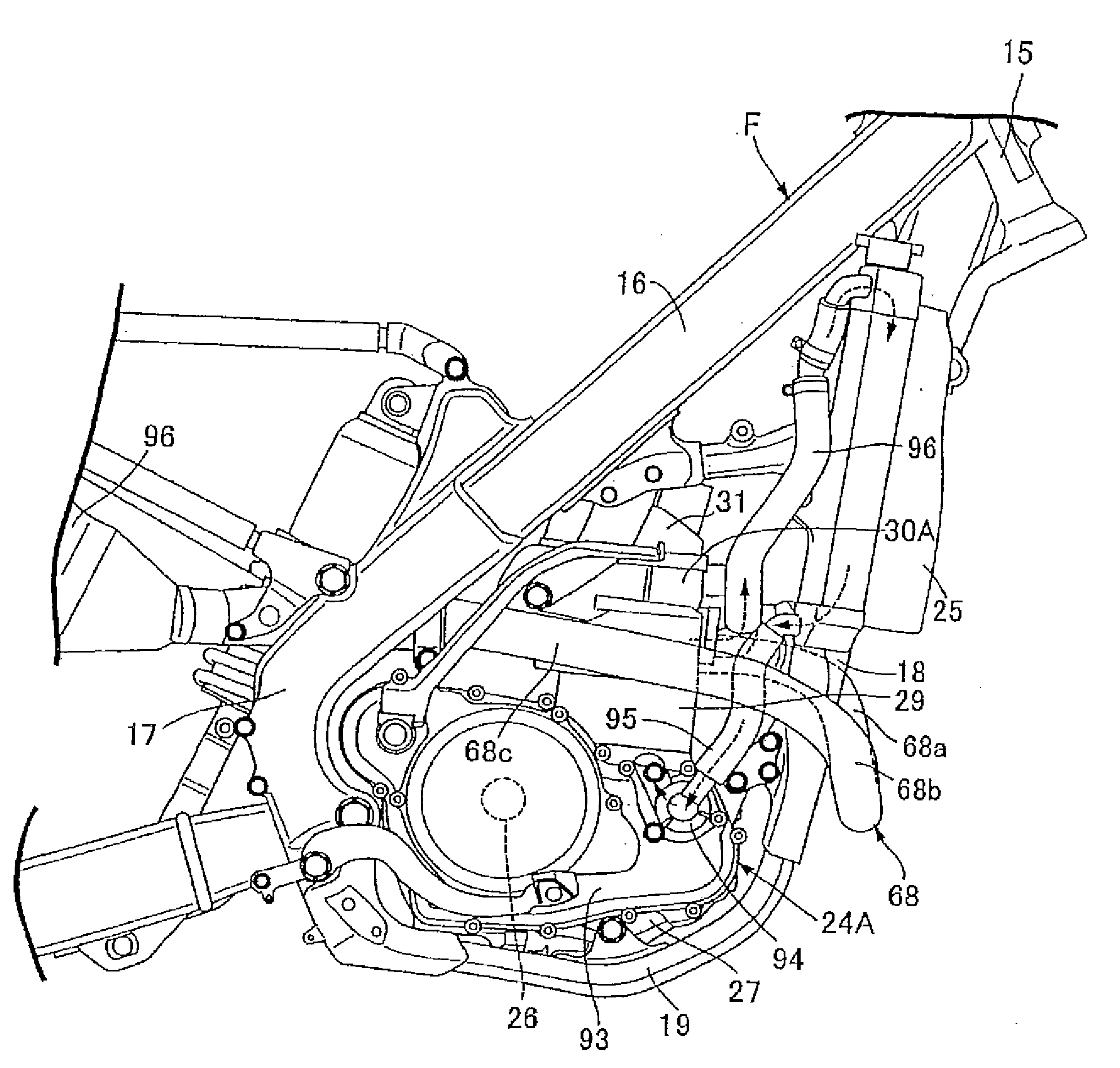
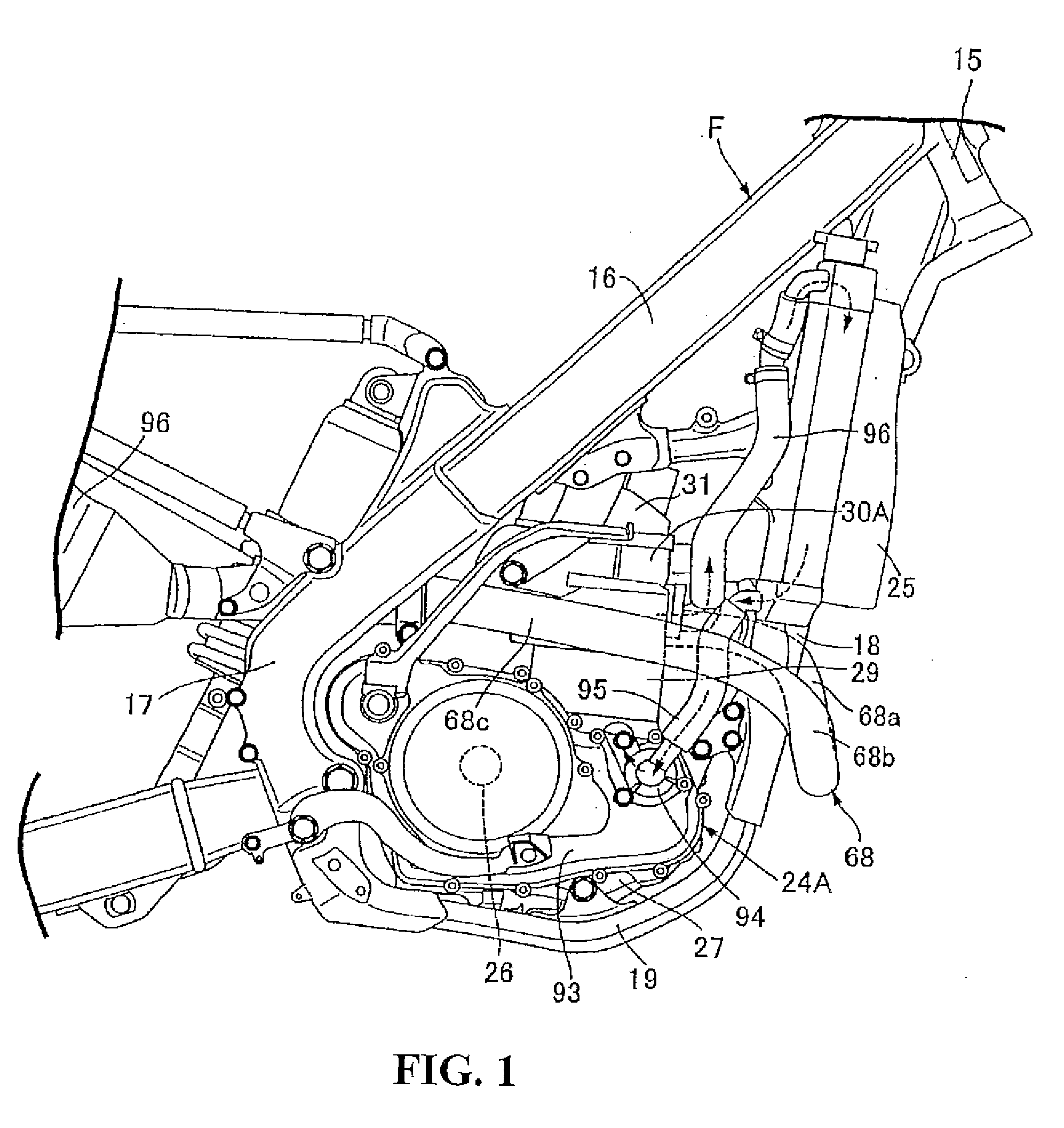
[0039]Referring first to FIG. 1, a body frame F of a motorcycle, a small-sized vehicle, includes a head pipe 15 provided at a front end; a pair of left and right main frames 16 extending rearward downward from the head pipe 15; a pair of left and right pivot plates 17 joined respectively to the rear portions of the main frames 16 and extending downward; a down frame 18 extending downward from the head pipe 15; and a pair of left and right lower frames 19 connecting the lower end of the down frame 18 with both the pivot plates 17. An engine body 24A of a water-cooled 4-cycle single-cylinder engine is carried by the body frame F so as to be disposed in a space surrounded by the main frames 16, the pivot plates 17, the down frame 18 and the lower frames 19. Radiators 25 are separately disposed forward of the engine body 24A to lie on either side of the down frame 18 and carried by the down frame 18.

[0040]Wit...

Example

[0087]FIGS. 8 through 10(a) and 10(b) illustrate a second embodiment of the present invention. FIG. 8 is a longitudinal cross-sectional left-lateral view of a 4-cycle engine corresponding to that of FIG. 2. FIG. 9 is an enlarged cross-sectional view taken along line 9-9 of FIG. 8. FIGS. 10(a) and 10(b) are enlarged views of an essential portion of a rotary valve in FIG. 8, for assistance in explaining respective states, when the valve is fully opened FIG. 10(a) and when fully closed FIG. 10(b).

[0088]Incidentally, the portions corresponding to those of the first embodiment are only indicated with like reference numerals and their explanations are omitted.

[0089]An engine body 24B includes a crankcase 27, a cylinder block 29, a cylinder head 30B, and a head cover 31. The crankcase 27 rotatably supports a crankshaft 26 with an axis extending in the left-right direction of the motorcycle. The cylinder block 29 has a cylinder bore 28 and is joined to the upper portion of the crankcase 27....

Example

[0103]According to the third embodiment, it is possible to avoid the interference between the cylinder head 30C of the valve housing 115 and the cylinder block 29. In addition, the rotary valve 71 can be isolated from a combustion chamber 34 (see the first embodiment) to be prevented from being raised to a high temperature.

[0104]FIG. 13 is a cross-sectional view corresponding to FIG. 3 and illustrating a fourth embodiment of the present invention. Portions corresponding to those in the first embodiment are indicated with like reference numerals and their detailed explanations are omitted.

[0105]A single exhaust port 116 is provided on a cylinder head 30D of an engine body 24D so as to commonly-communicate with the exhaust valve ports 37 (see the first embodiment). An exhaust side connection pipe 117 is provided integrally with the cylinder head 30D so as to form part of the exhaust port 116 and to project forward from the front lateral surface of the cylinder head 30D. An exhaust pip...


PUM


Abstract

An exhaust control device for a vehicle engine includes an exhaust control valve capable of changing the opening area of an exhaust passage. The exhaust control valve is disposed in exhaust passage forming means so as to be able to change a bent-internal side partial passage sectional area of the passage sectional area of an exhaust passage. Specifically the exhaust control valve is disposed at a bent portion of the exhaust passage that is closest to an exhaust valve port. With this configuration, the exhaust flow rate can be controlled satisfactorily.

Description

CROSS-REFERENCE TO RELATED APPLICATION[0001]The present application claims priority tinder 35 U.S.C. §119 to Japanese Patent Application No. 2007-256531, filed Sep. 28, 2007, the entire contents of which are hereby incorporated by reference.BACKGROUND OF THE INVENTION[0002]1. Field of the Invention[0003]The present invention relates to an exhaust control device for a vehicle engine, in which an exhaust valve capable of opening and closing an exhaust valve port provided in a cylinder head to face a combustion chamber is provided in the cylinder head so as to be able to be operatively opened and closed and an exhaust control valve capable of changing the opening area of an exhaust passage is disposed in exhaust passage forming means forming the exhaust passage that has a bent portion and is continuous with the exhaust valve port.[0004]2. Description of Background Art[0005]Japanese Patent Laid-Open No. Hei 2-049936 discloses an exhaust control device for a vehicle engine in which an ex...

Claims


Application Information

Patent Timeline
IPC IPC(8): F01N7/00F02D9/04F02D9/10F02D9/16F02D45/00
CPCF01N2240/36F02D9/1065F02D9/101F02D9/04
Inventor TSUBAKINO, YUKIHIROYASUI, SHINSUKEAZUMAGAKITO, ISAO
Owner HONDA MOTOR CO LTD
Why Eureka
Try Eureka