Exhaust control device for vehicle engine

a technology for controlling devices and exhaust, which is applied in the direction of electrical control, process and machine control, etc., can solve the problems of difficulty in controlling the exhaust flow rate and flow with accuracy, and achieve satisfactory exhaust control, high exhaust flow rate, and reduction of exhaust volume

Inactive Publication Date: 2012-11-06
HONDA MOTOR CO LTD
View PDF12 Cites 0 Cited by
  • Summary
  • Abstract
  • Description
  • Claims
  • Application Information

AI Technical Summary

Benefits of technology

[0014]The exhaust control valve changes the bent-internal side partial passage sectional area, of a passage sectional area of the exhaust passage, at the bent portion closest to the exhaust valve port. In other wards, the exhaust control valve is disposed at a portion where it is close to the combustion chamber and the exhaust flow rate is high even located on the bent-internal side. Thus, it is possible to produce an exhaust control effect at a maximum without enlargement of the exhaust control valve. In the state where the exhaust control valve is closed, exhaust flows only on the bent-external side, of the bent portion, where the exhaust flow rate is high. Thus, it is possible for the exhaust control valve to reduce the amount of exhaust while maintaining the exhaust flow rate. The occurrence of turbulent flow is suppressed while relieving the turbulence of exhaust flowing on the bent-external side in the bent portion, thereby enabling satisfactory exhaust control. In addition, since the exhaust control valve is located at a position close to the combustion chamber, it is possible to suppress the blow-by of fresh air resulting from the pressure control inside the combustion chamber by the exhaust control valve and from the overlapping of the opening timing of the exhaust valve and the intake valve.
[0015]In addition, the exhaust control valve is a rotary valve having a wall that is continuously flush with the inner surface of the exhaust passage when fully opened and is smoothly continuous with the inner surface of the exhaust passage on the upstream side of the exhaust control valve when closed. When fully opened, the exhaust control valve will not reduce the exhaust passage sectional area. During the high-speed operation of the engine, the exhaust control valve is fully opened. During the mid- and low-speed operation, the exhaust control valve is brought into the fully closed state where the passage sectional area of the exhaust passage is closed half or more thereof. Thus, during the high-speed operation, it is possible to improve the discharge of the exhaust from the combustion chamber without reducing the sectional area of the exhaust passage and to improve combustion efficiency by allowing fresh air to effectively flow in the combustion engine. In addition, during mid- and low-speed operation, the pressure in the combustion chamber is increased while preventing the blow-by of fresh air by retarding the discharge of the exhaust from the combustion engine, thereby increasing engine power.
[0016]Further, it is possible to exercise optimum opening and closing control on the exhaust control valve conforming to at least one of throttle opening, i.e., an index indicating the state of the combustion chamber and the engine revolutions, and the gear position of the transmission.
[0017]Still further, it is possible to apply engine brake during deceleration by the exhaust control valve which intends to increase the engine power.
[0018]Still further, it is possible to make the grip of the wheel satisfactory by temporarily closing the exhaust control valve during sudden acceleration to temporarily lowering the power without impairing acceleration-operational feeling.

Problems solved by technology

Thus, because of the nonconstant exhaust flow rate, it is difficult to control the exhaust flow rate and flow with accuracy.

Method used


Image

  • Exhaust control device for vehicle engine
  • Exhaust control device for vehicle engine
  • Exhaust control device for vehicle engine

Examples


first embodiment

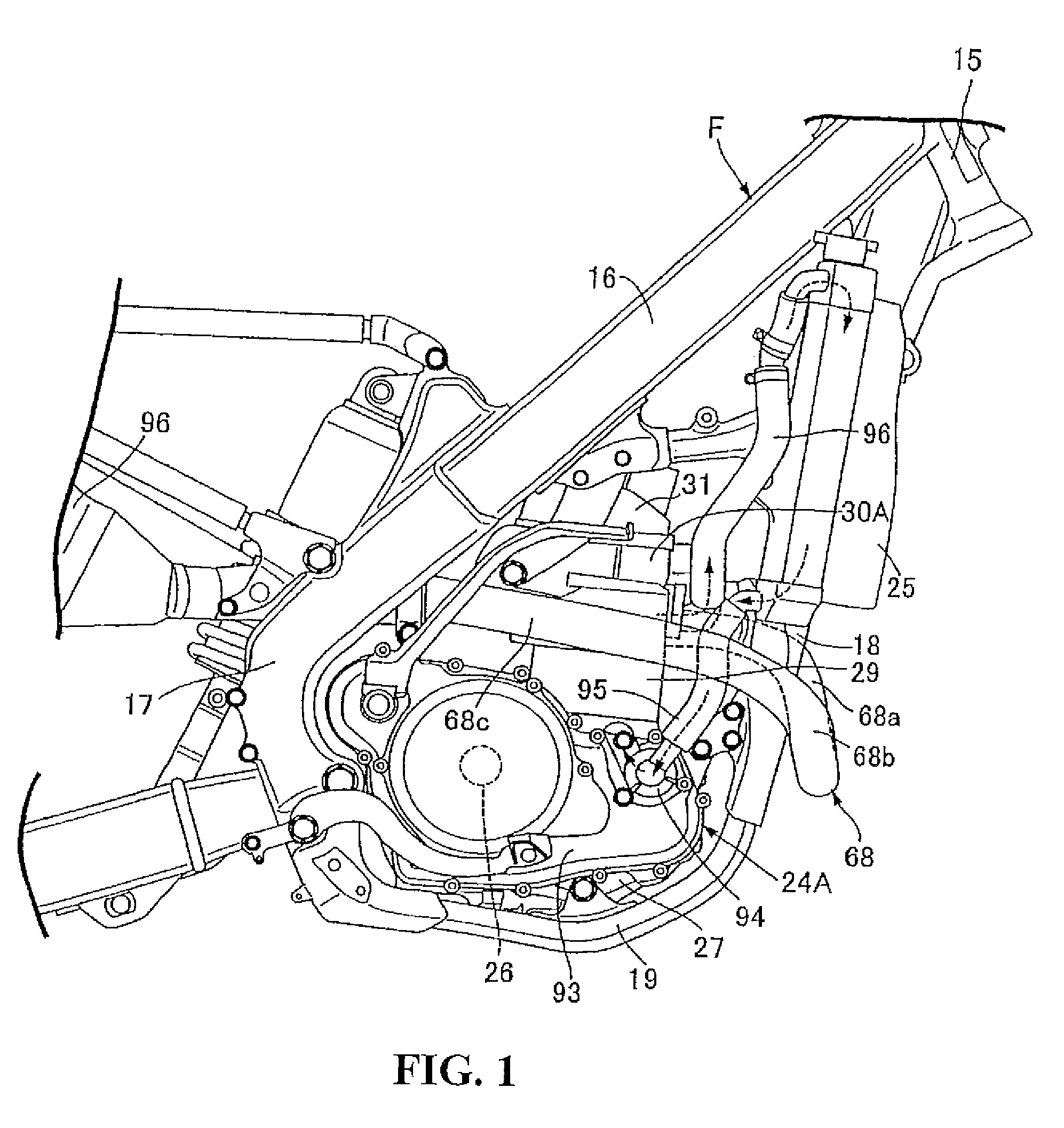
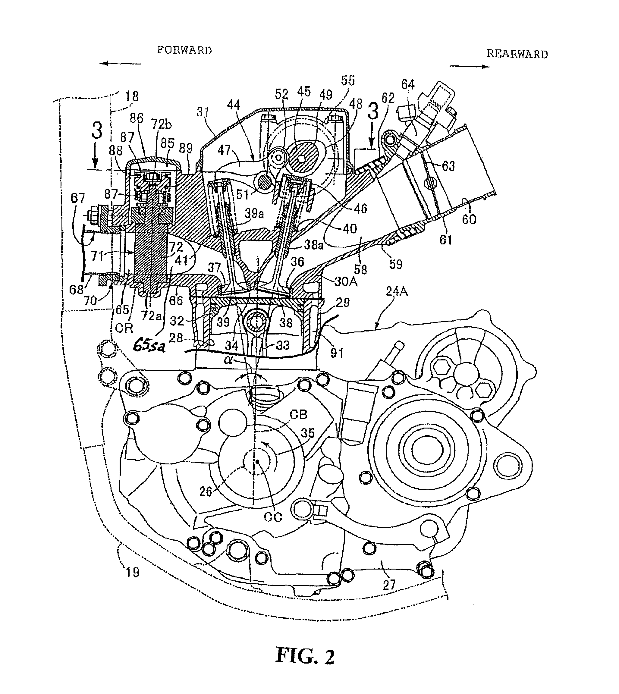
[0038]FIGS. 1 through 7 illustrate the present invention.

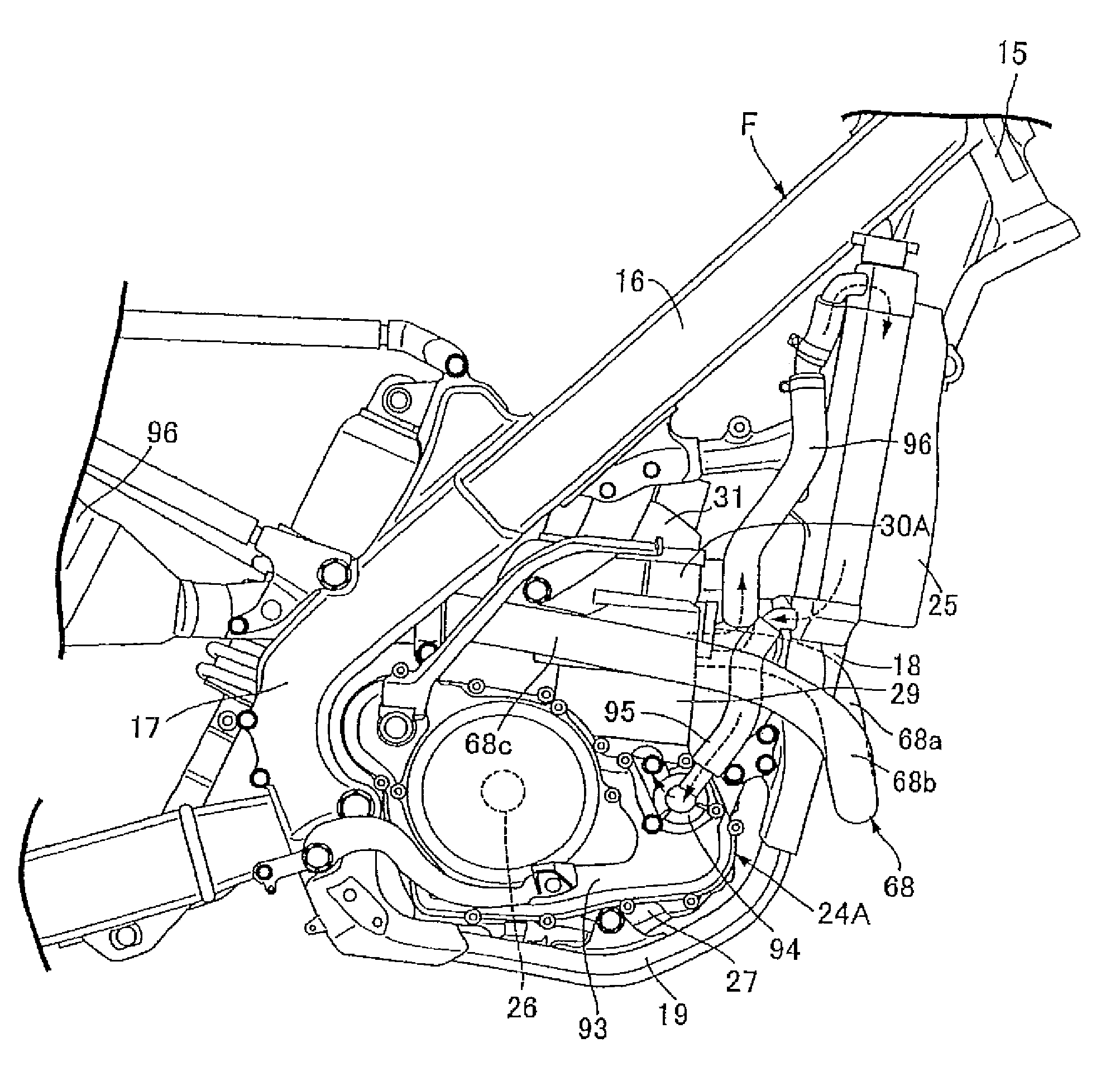
[0039]Referring first to FIG. 1, a body frame F of a motorcycle, a small-sized vehicle, includes a head pipe 15 provided at a front end; a pair of left and right main frames 16 extending rearward downward from the head pipe 15; a pair of left and right pivot plates 17 joined respectively to the rear portions of the main frames 16 and extending downward; a down frame 18 extending downward from the head pipe 15; and a pair of left and right lower frames 19 connecting the lower end of the down frame 18 with both the pivot plates 17. An engine body 24A of a water-cooled 4-cycle single-cylinder engine is carried by the body frame F so as to be disposed in a space surrounded by the main frames 16, the pivot plates 17, the down frame 18 and the lower frames 19. Radiators 25 are separately disposed forward of the engine body 24A to lie on either side of the down frame 18 and carried by the down frame 18.

[0040]With additional reference...

second embodiment

[0087]FIGS. 8 through 10(a) and 10(b) illustrate the present invention. FIG. 8 is a longitudinal cross-sectional left-lateral view of a 4-cycle engine corresponding to that of FIG. 2. FIG. 9 is an enlarged cross-sectional view taken along line 9-9 of FIG. 8. FIGS. 10(a) and 10(b) are enlarged views of an essential portion of a rotary valve in FIG. 8, for assistance in explaining respective states, when the valve is fully opened FIG. 10(a) and when fully closed FIG. 10(b).

[0088]Incidentally, the portions corresponding to those of the first embodiment are only indicated with like reference numerals and their explanations are omitted.

[0089]An engine body 24B includes a crankcase 27, a cylinder block 29, a cylinder head 30B, and a head cover 31. The crankcase 27 rotatably supports a crankshaft 26 with an axis extending in the left-right direction of the motorcycle. The cylinder block 29 has a cylinder bore 28 and is joined to the upper portion of the crankcase 27. The cylinder head 30B ...

fourth embodiment

[0110] since the rotary valve 71 is disposed in the exhaust port 116, the passage sectional area of the exhaust port 116 will not be reduced when the rotary valve 71 is fully opened. In addition, although the relatively large rotary valve 71 is disposed in the exhaust side connection pipe 117 of the cylinder head 30D, the rotary valve 71 is disposed in the exhaust side connection pipe 117 at a position offset from the center CL of the exhaust port 116 toward the side opposite to the cam chain chamber 57. Thus, it is easy to avoid the interference between the rotary valve 71 and a driven sprocket 55 provided on the cam shaft 45 to constitute part of the timing transmission mechanism 53. This can downsize the cylinder head 30D.


PUM


Abstract

An exhaust control device for a vehicle engine includes an exhaust control valve capable of changing the opening area of an exhaust passage. The exhaust control valve is disposed in exhaust passage forming means so as to be able to change a bent-internal side partial passage sectional area of the passage sectional area of an exhaust passage. Specifically the exhaust control valve is disposed at a bent portion of the exhaust passage that is closest to an exhaust valve port. With this configuration, the exhaust flow rate can be controlled satisfactorily.

Description

CROSS-REFERENCE TO RELATED APPLICATION[0001]The present application claims priority tinder 35 U.S.C. §119 to Japanese Patent Application No. 2007-256531, filed Sep. 28, 2007, the entire contents of which are hereby incorporated by reference.BACKGROUND OF THE INVENTION[0002]1. Field of the Invention[0003]The present invention relates to an exhaust control device for a vehicle engine, in which an exhaust valve capable of opening and closing an exhaust valve port provided in a cylinder head to face a combustion chamber is provided in the cylinder head so as to be able to be operatively opened and closed and an exhaust control valve capable of changing the opening area of an exhaust passage is disposed in exhaust passage forming means forming the exhaust passage that has a bent portion and is continuous with the exhaust valve port.[0004]2. Description of Background Art[0005]Japanese Patent Laid-Open No. Hei 2-049936 discloses an exhaust control device for a vehicle engine in which an ex...

Claims


Application Information

Patent Timeline
Patent Type & Authority Patents(United States)
IPC IPC(8): F01N1/00F01L7/00G05D7/01F02D9/04F02D9/10F02D9/16F02D45/00
CPCF02D9/04F02D9/101F02D9/1065F01N2240/36
Inventor TSUBAKINO, YUKIHIROYASUI, SHINSUKEAZUMAGAKITO, ISAO
Owner HONDA MOTOR CO LTD
Why Eureka
Try Eureka