Digital Controlled Solenoid Capillary Tube Metering Devices of Refrigeration Systems

Active Publication Date: 2021-05-06
ZHONG LEI
View PDF0 Cites 1 Cited by
  • Summary
  • Abstract
  • Description
  • Claims
  • Application Information

AI Technical Summary

Benefits of technology

[0026]The DCSCEV, because of its robust abilities of digital control, would not need sophisticated valve structures, and would require only a few sizes for various a

Problems solved by technology

This gas bubble reduces the portion of refrigerant liquid and reduce the refrigeration effectiveness of the system.
Because the conventional expansion valves need to provide the precise amount of refrigerant liquid flow, the valve ports must be made with high accuracy, which unavoidably increases valve costs.
Since the conventional exp

Method used


Image

  • Digital Controlled Solenoid Capillary Tube Metering Devices of Refrigeration Systems
  • Digital Controlled Solenoid Capillary Tube Metering Devices of Refrigeration Systems
  • Digital Controlled Solenoid Capillary Tube Metering Devices of Refrigeration Systems

Examples


Embodiment Construction

[0033]While this invention is susceptible of embodiment in many different forms, there are shown in the drawings, and will be described herein in detail, specific embodiments thereof with the understanding that the present disclosure is to be considered as an exemplification of the principles of the invention and is not intended to limit the invention to the specific embodiments illustrated.

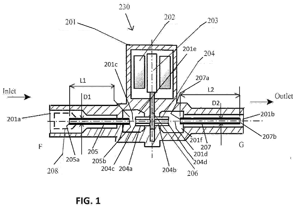
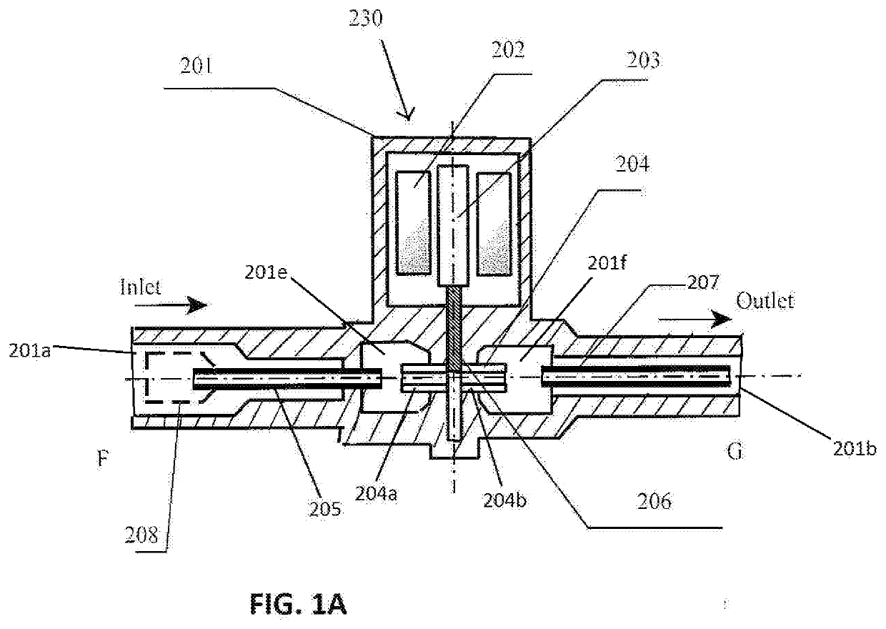
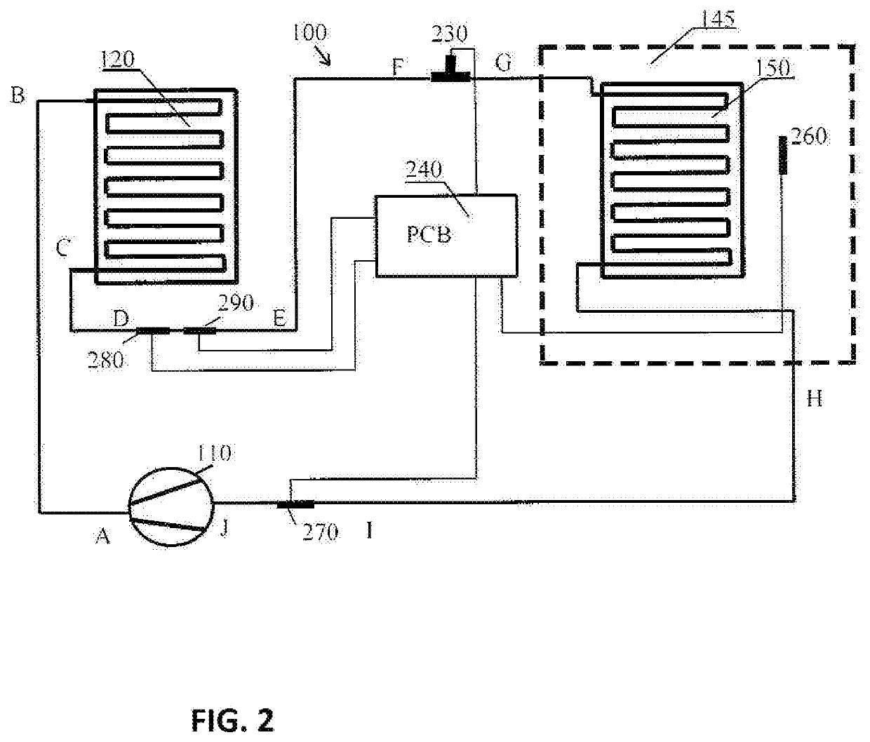
[0034]FIG. 1 shows the structure of a valve 230, such as a solenoid capillary tube expansion valve 230 of a DCSCEV. The valve 230 is controlled by a controller 240 in the form of a printed circuit board (PCB) or other digital electronics device. The valve 230 can be digitally controlled to completely either open or close for selected durations according to rules set by the controller 240 in response to sensors.

[0035]The valve 230 includes a body 201 having a valve inlet 201a and a valve outlet 201b, a coil 202, a plunger 203, a seat 204 having an inlet seat tube 204a and an outlet seat tube 204b,...


PUM


Abstract

A refrigeration system includes a compressor; a condenser; an expansion valve having a body with an expansion valve inlet and an expansion valve outlet; an evaporator all arranged in a refrigeration circuit; and a controller. The expansion valve body has a pathway comprising an inlet body capillary tube flow-connected to the expansion valve inlet, and an outlet body capillary tube flow-connected to the expansion valve outlet. The expansion valve comprises a solenoid operated valve element that is selectively positionable between the inlet body capillary tube outlet and the outlet body capillary tube inlet. The controller digitally controls the valve element to position the valve element either to allow flow through the pathway in an open position or to block flow through the pathway in a closed position.

Description

BACKGROUND OF THE INVENTION[0001]The present invention is directed to refrigeration systems, particularly to an improved mechanical refrigeration system.[0002]A conventional mechanical refrigeration system 20 is shown in FIG. 4. The refrigeration system comprises a compressor 24, a condenser 26 having a condenser coil 27, a metering device 28 such as an expansion valve, and an evaporator 30 having an evaporator coil 32. Refrigerant gas is drawn into the compressor at point J, is compressed at point A and delivered into the condenser coil at point B. Air can be blown over the condenser coil, or simply ambient air surrounds the condenser coil, wherein the air absorbs heat from the refrigerant within the coil and the refrigerant is thus cooled. The refrigerant gas is condensed into a liquid within the condenser. The liquid refrigerant from the condenser is subcooled and delivered into the metering device at point F and then enters into the evaporator at point G. In the evaporator 30, a...

Claims


Application Information

Patent Timeline
IPC IPC(8): F25B41/06G05D23/19F25B41/04
CPCF25B41/062G05D23/1917F25B2341/062F25B41/04F25B2341/0652G05D23/1919F25B41/39F25B41/37F25B41/345F25B2700/2104F25B2700/21163F25B2700/195F25B2700/1933F25B2600/2513F25B41/31F25B41/20F25B41/347
Inventor ZHONG, LEI
Owner ZHONG LEI
Why Eureka
Try Eureka