Filter for water treatment and filter apparatus comprising same

a filter and water treatment technology, applied in the direction of filtration separation, membrane technology, separation processes, etc., can solve the problems of reducing filtration efficiency, micropores formed in the filter are clogged by foreign substances, and the micropores must be frequently backwashed, so as to reduce the formation of vortices, reduce the flow velocity of the laminar (streamline) flow, and increase the amount of filtration

Inactive Publication Date: 2021-05-27
ARUN CO LTD
View PDF0 Cites 0 Cited by
  • Summary
  • Abstract
  • Description
  • Claims
  • Application Information

AI Technical Summary

Benefits of technology

[0029]According to at least one of embodiments of the present invention, a filter for water treatment and a filter apparatus comprising same can have the following effects.
[0030]According to at least one of embodiments of the present invention, the filter and the filter apparatus can have an effect of removing foreign substances adhered to the filter during the filtration process.
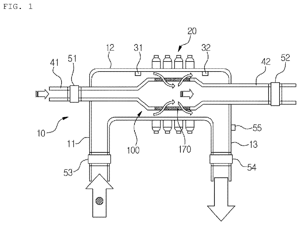
[0031]According to at least one of embodiments of the present invention, the filter and the filter apparatus can have an effect of increasing the amount of filtration by reducing the formation of vortices in the fluid passing through the filter. According to at least one of embodiments of the present invention, the formation of vortices in a laminar (streamline) flow between a filter and a distribution duct in which the filter is accommodated is reduced, thereby the filter and the filter apparatus can have an effect of minimizing the decrease in the flow velocity of the laminar (streamline) flow. According to at least one of embodiments of the present invention, the filter and the filter apparatus can have an effect of removing the clogging of the filter at an appropriate time by detecting clogging of the filter.

Problems solved by technology

When such a filter performs a filtration process to remove foreign substances from the supplied water, micropores formed in the filter are clogged by foreign substances.
However, in such a filter, the micropores formed in the filter are opened parallel to the direction of fluid transfer, and the diameter of the inner wall of the groove forming the micropores is enlarged, reduced, and enlarged in the shape of an hourglass so that the foreign substances are often attached to the inner wall of the groove, and thus, there is a problem in that micropores must be frequently backwashed by a pulsed air in a state where the filtering process is stopped.
Moreover, foreign substances sticking to the inner wall of the groove located at the upstream end in the filtering direction have a problem that they are not separated from the inner wall of the groove by backwashing.
However, when a fluid containing a high concentration of solid foreign substances is filtered, there has been a problem in that air bubbles contained in the high concentration fluid adhere to the inner and outer surfaces of the filter and the inner surfaces of the plurality of openings formed in the filter, and generate a surface tension which causes the solid foreign substances contained in the fluid to adhere to the filter, thereby reducing the filtration efficiency.
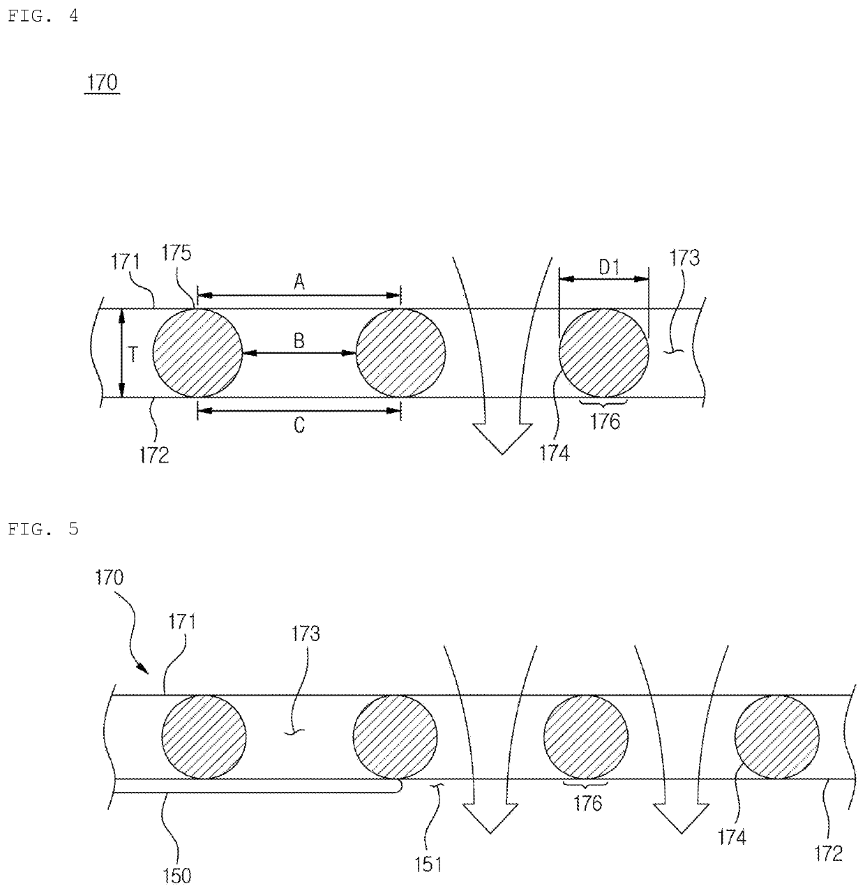
There has been a problem in that the vortices reduce the amount of filtration by acting as a resistance against the fluid passing through the opening.
There has been a problem in that the generated vortices act as resistance against the laminar (streamline) flow and eventually reduce the flow velocity of the entire laminar (streamline) flow, thereby degrading the function of removing foreign substances (cake) in the laminar (streamline) flow.

Method used


Image

  • Filter for water treatment and filter apparatus comprising same
  • Filter for water treatment and filter apparatus comprising same
  • Filter for water treatment and filter apparatus comprising same

Examples


Embodiment Construction

[0042]It should be understood that the embodiments described hereinafter are illustratively shown to aid understanding of the invention, and the present invention may be implemented with various modifications different from the embodiments described herein. However, in describing the present invention, when it is determined that a detailed description of a well-known function or component may unnecessarily obscure the gist of the present invention, the detailed description and detailed illustration thereof will be omitted. In addition, the accompanying drawings are not drawn to scale to aid understanding of the invention, but dimensions of some components may be exaggeratedly illustrated.

[0043]The terms ‘first’ and ‘second’ used in the present application may be used to describe various components, but the components should not be limited by the terms. The terms are only used for the purpose of distinguishing one component from another component.

[0044]In addition, terms used in the ...


PUM

PropertyMeasurementUnit
diameteraaaaaaaaaa
diameteraaaaaaaaaa
diameteraaaaaaaaaa

Abstract

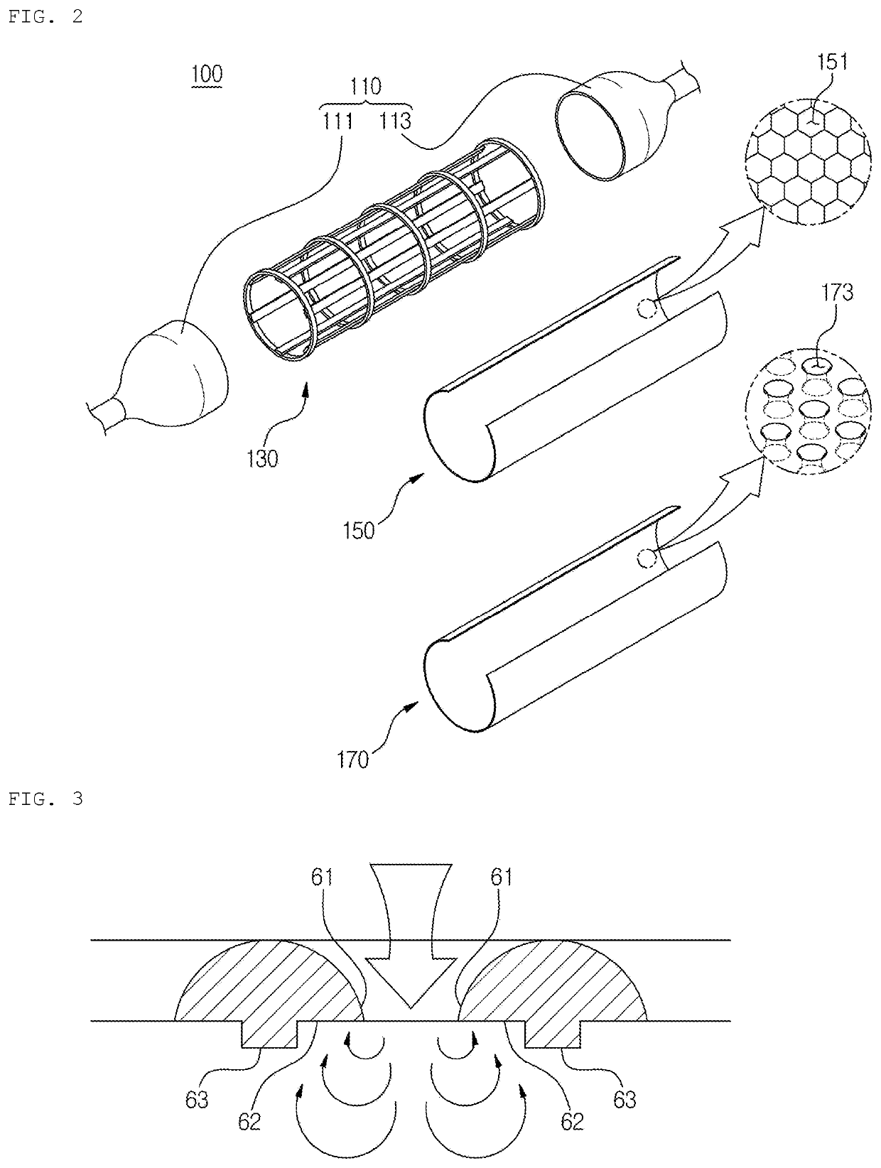
A filter for water treatment exhibiting high filtering capability by preventing vortices, and a filter apparatus including same is provided. The filter for water treatment, which is a cross flow type filter, includes a metal thin plate and a plurality of micropores passing through the metal thin plate so as to filter water flowing on one side of the metal thin plate. A micropore includes an inlet port which is formed on one surface of the metal thin plate and through which water flows in; a discharge port which is formed on the other surface positioned opposite from the one surface of the metal thin plate, and through which the water flowing in through the inlet port is discharged; and a curved portion convexly curved towards the inside of the micropore connects the inlet port and the discharge port. The curved portion and the other surface form a singular surface.

Description

TECHNICAL FIELD[0001]The present invention relates to a water treatment filter and a filter apparatus comprising same, and more particularly, relates to a water treatment filter exhibiting high filtering capability by preventing vortices and a filter apparatus comprising same.BACKGROUND ART OF THE INVENTION[0002]The filter is made of a plate or tubular material with a porous plate material, and is interposed in the tubular portion through which the fluid flows to perform the function of filtering foreign substances contained in the flowing fluid.[0003]When such a filter performs a filtration process to remove foreign substances from the supplied water, micropores formed in the filter are clogged by foreign substances.[0004]A filter to prevent a phenomenon that such micropores are blocked by foreign substances, that is, filter clogging phenomenon, is disclosed in Korean Patent Publication No. 10-2006-0037051. The disclosed filter comprises a cylindrical support frame having an openin...

Claims


Application Information

Patent Timeline
Patent Type & Authority Applications(United States)
IPC IPC(8): B01D39/10B01D37/04B01D35/30B01D35/20B01D35/16
CPCB01D39/10B01D37/046B01D2201/18B01D35/20B01D35/16B01D35/30B01D37/04B01D29/23B01D2239/1216B01D29/72B01D2201/184B01D35/143
Inventor OH, SOON-BONG
Owner ARUN CO LTD
Why Eureka
Try Eureka