Zero emission propulsion systems and generator sets using ammonia as fuel

a technology of ammonia fuel and propulsion system, which is applied in the direction of machines/engines, mechanical equipment, electric control, etc., can solve the problems of difficult ignition of ammonia (nhsub>3/sub>), and achieve the effect of good ignition of the air/ammonia (nh3) mixtur

Active Publication Date: 2021-06-03
HEGGEN LARS HARALD
View PDF0 Cites 14 Cited by
  • Summary
  • Abstract
  • Description
  • Claims
  • Application Information

AI Technical Summary

Benefits of technology

[0038]In order to ensure good ignition of an air/ammonia (NH3) mixture in an internal combustion engine, it would be advantageous to use a separate pilot ignition system consisting of a separate prechamber with its own air or air/fuel intake. An air/hydrogen (H2) mixture can be used for pilot ignition of zero emission engines, where such an air/hydrogen (H2) mixture is sucked into a prechamber in connection with the cylinder and ignited by spark ignition. Alternatively, other bio or

Problems solved by technology

The disadvantage is that ammoni

Method used


Image

  • Zero emission propulsion systems and generator sets using ammonia as fuel
  • Zero emission propulsion systems and generator sets using ammonia as fuel
  • Zero emission propulsion systems and generator sets using ammonia as fuel

Examples


Embodiment Construction

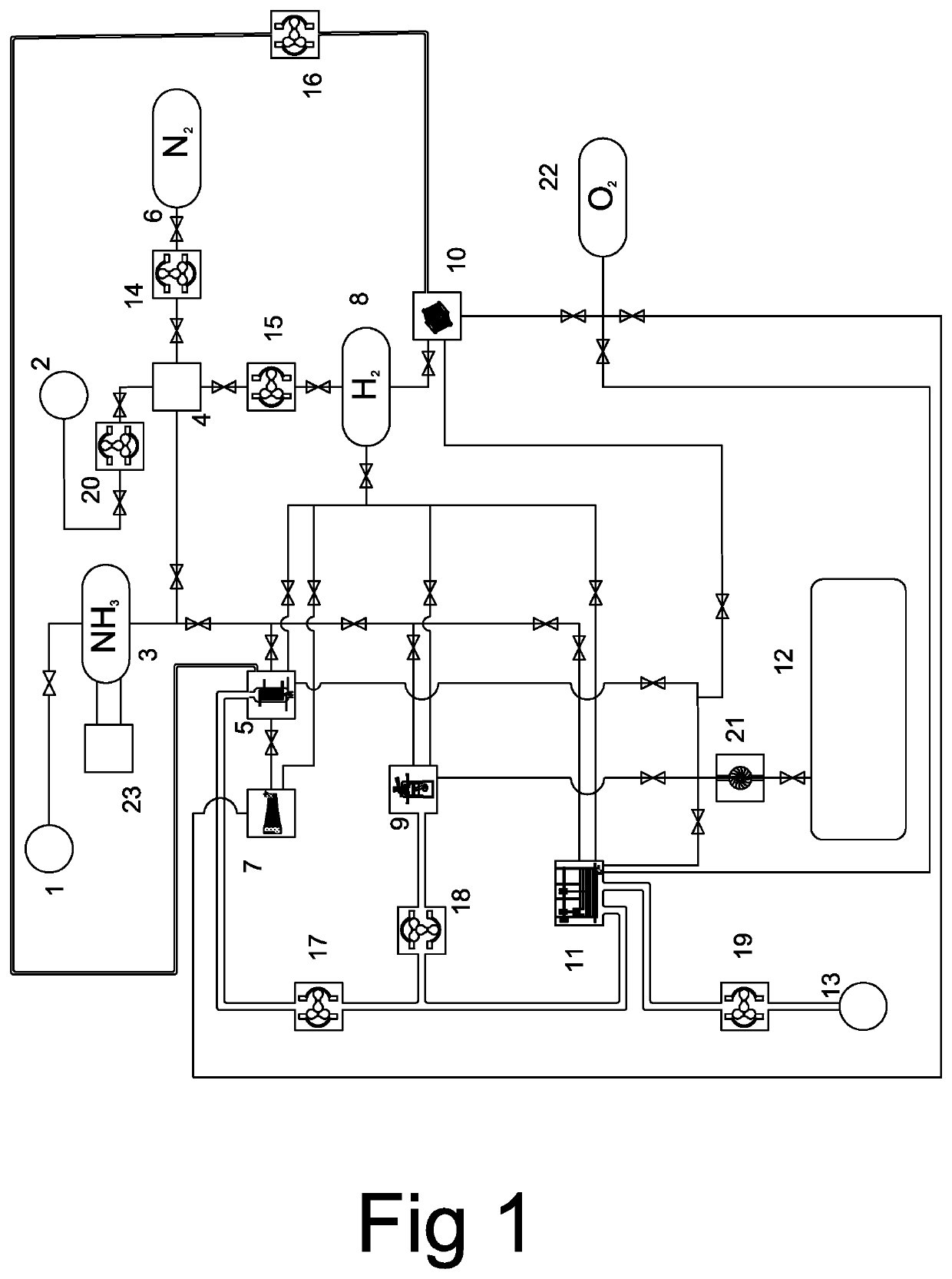
[0045]1) Ammonia (NH3) fuelling.[0046]Ammonia (NH3) fuelling will normally take place at a pressure of approximately 10 bar, which is the vapour pressure of ammonia (NH3) at approx. 25° C. Here, different fuelling devices can be used depending on whether the ammonia (NH3) is stored as a liquid under pressure (at about 10 bar at 25° C.) or cooled (at about −33.4° C. at 1 atm). There will also be different fuelling devices depending on the type of vehicle or vessel. For vehicles, the same refuelling device as for LPG could be used.

[0047]2) Venting nitrogen (N2) (N2 from exhaust).[0048]This is the venting / exhaust of nitrogen (N2) from the hydrogen reactor (4). If ammonia (NH3) is cleaved to produce nitrogen (N2) and hydrogen (H2), excess nitrogen (N2) will be vented to air.

[0049]3) Fuel tank(s) for ammonia (NH3).[0050]Tank for storage of ammonia (NH3). The ammonia (NH3) is stored in liquid form either under pressure (at approx. 10 bar) or chilled (at approx. −33.4° C. at 1 atm). Altern...


PUM


Abstract

The present invention relates to a zero emission propulsion system and generator sets using ammonia (NH3) as fuel for engines and power plants such as steam boilers (5) for steam turbines (7), piston engines (9), fuel cells (10) or Stirling engines (11). Due to the poor flammability of ammonia (NH3), a hydrogen reactor (4) can split ammonia (NH3) into hydrogen (H2) and nitrogen (N2). The hydrogen (H2) can be placed in a hydrogen tank (8) for intermediate storage and the nitrogen can be stored in a nitrogen tank (6). The hydrogen (H2) could be mixed with ammonia (NH3) to improve flammability and thus facilitate the ignition of an air/ammonia (NH3) mixture in engines or power plants (5, 9, 11). Alternatively, hydrogen (¾) may be supplied in a separate fuel system (5-1, 9-5, 11-8) as a pilot fuel for pilot ignition of an air/ammonia (NH3) mixture. The hydrogen (H2) can also be used in AIP systems along with oxygen (O2) from an oxygen tank (22). The hydrogen (H2) will then be used for fuel cells (10), for combustion in a steam turbine inlet/high pressure side (7-1), or in a Stirling engine (11). In addition to hydrogen (H2), other bio and fossil fuels from the fuel tank (12) can be used as pilot fuel for pilot ignition of an air/ammonia (NH3) mixture. The advantage of using existing bio or fossil fuels for pilot ignition is that engines or power plants (5, 9, 11) will have a pilot fuel system with sufficient capacity to maintain normal operations if ammonia (NH3) is not available. Alternatively, that engines or power plants (5, 9, 11) have an additional fuel system for existing bio or fossil fuels in order to maintain normal operations if ammonia (NH3) is not available. The nitrogen (N2) in the nitrogen tank (6) can be used as a gas in fire extinguishing systems or for submarine ballast tank blows.

Description

KNOWN TECHNOLOGY[0001]Zero emission systems are defined as energy systems that do not release CO2. Propulsion systems of this kind have become relevant since establishment of the relationship between the atmospheric CO2 content and global warming.[0002]The problem with using pure hydrogen (H2) as fuel is that, for most purposes, hydrogen (H2) must be stored as compressed gas. This makes the energy density relatively low. Leakage from tanks also becomes relatively large due to the size of the hydrogen atom which allows it to penetrate through most materials. In gas form, the density of hydrogen (H2) is low, resulting in low energy density. Hydrogen's (H2) boiling point (−252.9° C.) and melting point (−259.2° C.) makes it inconvenient to use hydrogen (H2) in liquid or solid form as fuel for most propulsion systems. Aerospace is one of the exceptions where both liquid and solid hydrogen (H2) are used.[0003]Ammonia (NH3) is therefore a better energy carrier. The main drawback is that it...

Claims


Application Information

Patent Timeline
IPC IPC(8): F02D19/06F02M21/02
CPCF02D19/0644F02D19/0671F02D41/0027F02M21/0215F02M21/0206F02D29/06Y02T10/30F02M25/12F02B19/10Y02T10/12F02D19/00F02D19/06F02M25/10F02B19/1028F02B19/108
Inventor HEGGEN, LARS HARALD
Owner HEGGEN LARS HARALD
Why Eureka
Try Eureka