Wireless Sensor

a sensor and wireless technology, applied in the field of wireless sensors, can solve the problems of limited use of existing commercial sensors in some types of machines, large size failure rate of existing commercial sensors, such as pressure sensors, to achieve the effect of saving power, increasing battery life, and preserving power

Pending Publication Date: 2021-06-10
BARNES GROUP
View PDF10 Cites 0 Cited by
  • Summary
  • Abstract
  • Description
  • Claims
  • Application Information

AI Technical Summary

Benefits of technology

[0034]In accordance with another and/or alternative non-limiting aspect of the present disclosure, the wireless sensor optionally includes a magnetic sensor or switch (e.g., Hall effect sensor/switch) used to cause the wireless sensor to 1) move from a deep sleep mode to a sleep mode or operational/run mode, and/or 2) move into a deep sleep mode from the sleep mode or operational/run mode. In one non-limiting embodiment, the wireless sensor can only be taken out of deep sleep mode and/or can only be placed into deep sleep mode by use of a magnet or magnetic device manually moved in contact with or into close proximity to the magnetic sensor or switch. In another non-limiting embodiment, the wireless sensor can be placed in deep sleep mode by manually placing a magnet or magnetic device in close proximity to the wireless sensor (e.g., within 0-5 ft (and all values and ranges therebetween) of the wireless sensor, less than 2 ft. of the wireless sensor) for a certain period of time (e.g., 0.01-60 seconds (and all values and ranges therebetween), at least 5 sec., at least 10 sec., at least 20 sec., at least 30 sec., etc.). The requirement to both places a magnet or magnetic device in close proximity to the wireless sensor for some minimum period of time reduces or prevents inadvertently placing the wireless sensor in deep sleep mode. Prior to the wireless sensor going into the deep sleep mode, the wireless sensor can optionally broadcast one or more signals indicating over a certain period of time (e.g., 1-30 sec. (and all values and ranges therebetween), etc.) that the wireless se

Problems solved by technology

However, the large size of these existing commercial sensors has limited their use in some types of machines.
Existing commercial sensors, such as pressure sensors, have also exhibited

Method used


Image

  • Wireless Sensor
  • Wireless Sensor
  • Wireless Sensor

Examples


Embodiment Construction

[0130]Although specific terms are used in the following description for the sake of clarity, these terms are intended to refer only to the particular structure of the embodiments selected for illustration in the drawings and are not intended to define or limit the scope of the disclosure. In the drawings and the following description below, it is to be understood that like numeric designations refer to components of like function.

[0131]The singular forms “a,”“an,” and “the” include plural referents unless the context clearly dictates otherwise.

[0132]As used in the specification and in the claims, the term “comprising” may include the embodiments “consisting of” and “consisting essentially of.” The terms “comprise(s),”“include(s),”“having,”“has,”“can,”“contain(s),” and variants thereof, as used herein, are intended to be open-ended transitional phrases, terms, or words that require the presence of the named ingredients / steps and permit the presence of other ingredients / steps. However...


PUM


Abstract

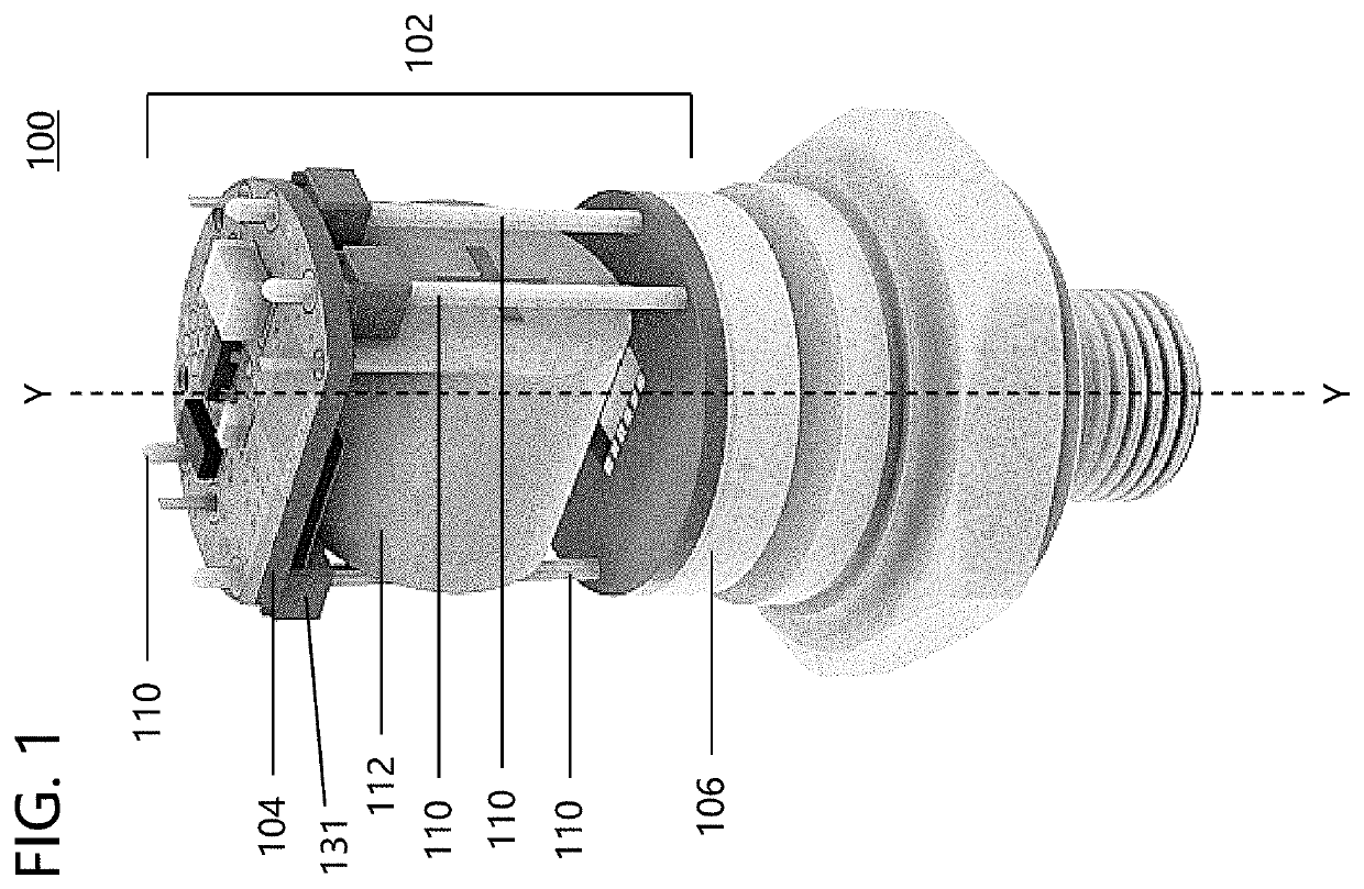
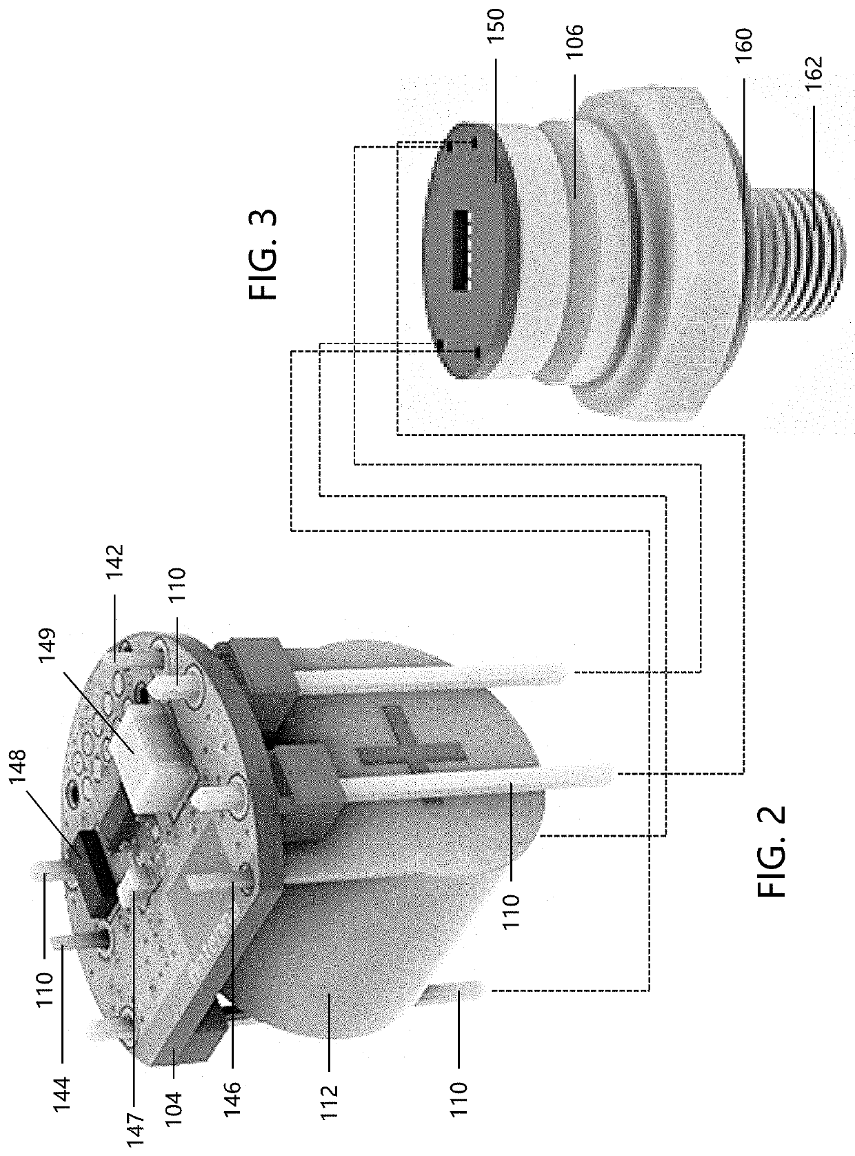
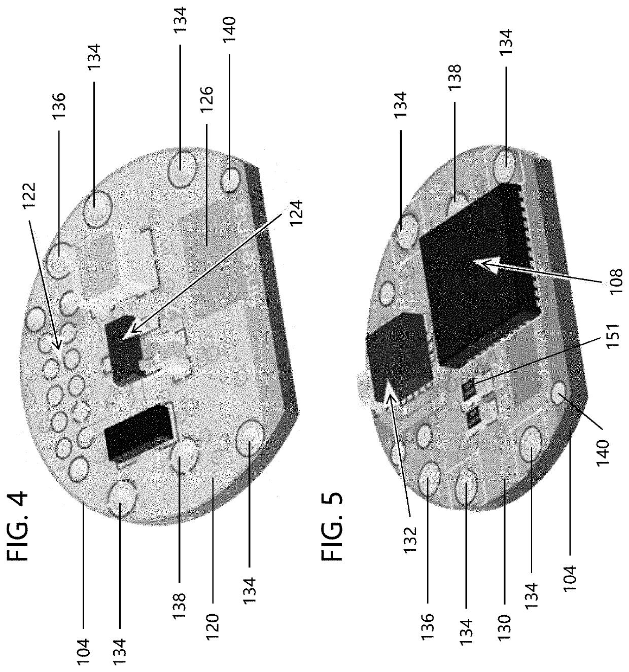
A wireless sensor for an associated machine or machine part which includes a communications module that wirelessly transmits data related to the associated machine or machine part. The communications module is mounted on the sensor and the sensor is disposed under the bottom side of the control circuitry. A sensor is configured to measure one or more properties of the associated machine or machine part.

Description

[0001]The present disclosure claims priority on U.S. Provisional Patent Application Ser. Nos. 62 / 945,999 filed Dec. 10, 2019 and 62 / 961,877 filed Jan. 16, 2020 which are incorporated herein by reference.[0002]The present disclosure sets forth devices, systems, and methods related to a wireless sensor adapted for determining, sensing / detecting, and / or measuring one or more properties (e.g., measuring pressure, measuring temperature, location, etc.) of an associated machine or a part of the associated machine. It finds particular application in conjunction with communication devices which transmit information related to the associated machine or part of the associated machine, and will be described with particular reference thereto. However, it is to be appreciated that the present exemplary embodiment is also amenable to other like applications.BACKGROUND[0003]Temperature and pressure sensor-type devices are known in the art for use with various types of machines and machine componen...

Claims


Application Information

Patent Timeline
IPC IPC(8): G01R33/07H04L29/08H04W52/02G01P15/14G01P15/18G01K7/00H04W4/38
CPCG01R33/07H04L67/12H04W52/0235H04W4/38G01P15/18G01K7/00G01P15/14G08C17/02G05B19/042G05B2219/15117G01D21/02G01R33/072G01R33/02G01R33/0088H04W4/70G01K1/024G05B19/0428H04L67/125
Inventor DARRAH, KEVIN R.CULBERTSON, MICHAEL O.REILLY, STEVEN J.KNIPL, JR., KELVIN L.
Owner BARNES GROUP
Why Eureka
Try Eureka