Unlock instant, AI-driven research and patent intelligence for your innovation.

Near field line pattern generator

a line pattern and near field technology, applied in the field of line pattern generators, can solve the problems of not being suitable for distance measurement or other analysis of objects in target area, not crisp lines,

Pending Publication Date: 2021-06-17
LUMILEDS
View PDF1 Cites 0 Cited by
  • Summary
  • Abstract
  • Description
  • Claims
  • Application Information

AI Technical Summary

Benefits of technology

The present patent is about a new line pattern generator that can be used to illuminate objects in a target area with a pattern of light. This generator uses a double grating to produce a pattern of light that can be focused along a target plane. The generator can be controlled to produce different patterns of light at different distances from the generator. The use of line pattern generators has advantages over lasers, as they are more cost- and energy-intensive. The technical effects of this patent are improved accuracy and efficiency in distance measurement and the ability to produce high-quality light patterns in a compact design.

Problems solved by technology

The light intensity fields 220 and 230 observed at 5 cm and 10 cm, respectively, from the double grating have faint line patterns, but the lines are not crisp, and may not be suitable for distance measurement or other analysis of objects in target area at these distances.

Method used


Image

  • Near field line pattern generator
  • Near field line pattern generator
  • Near field line pattern generator

Examples


example prior

Art Double Grating

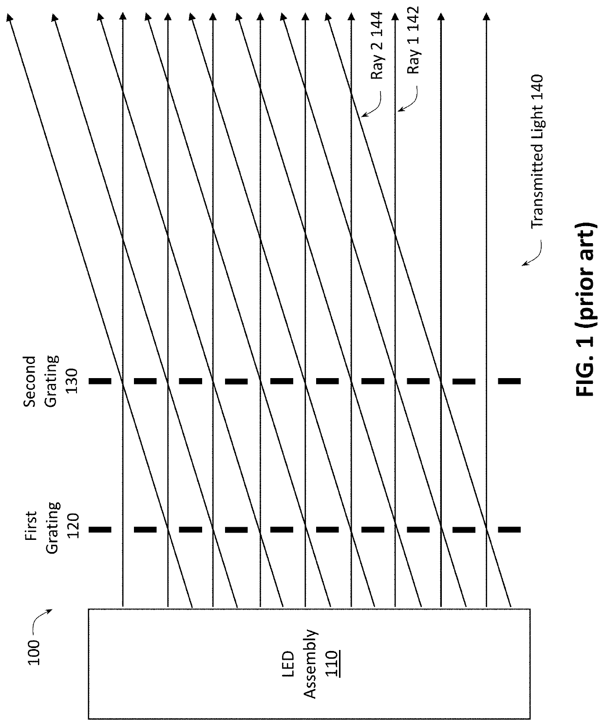
[0036]FIG. 1 provides a cross section of transmitted light passed through a prior art double grating. A light emitting diode (LED) assembly 110 emits light in the general direction of a double grating that includes a first grating 120 and second grating 130. The LED assembly 110 emits light rays at multiple angles and from multiple positions, as shown in FIG. 1. For example, the LED assembly 110 may be a collection of LEDs, each of which emits light rays at multiple angles. Two angles of light rays emitted by the LED assembly 110 are shown in FIG. 1; it should be understood that additional light rays at additional angles may also be emitted from the LED assembly 110.

[0037]The first grating 120 has a regular sequence of light transmitting sections and light blocking sections. The light transmitting sections and the light blocking sections are arranged at a first pitch. The second grating 130 is identical to the first grating 120, having the same pitch as the first g...

example simulation

Results for Line Pattern Generators

[0059]FIG. 7A provides light intensity fields at several distances for a double grating line pattern generator focused 5 cm from the line pattern generator, according to some embodiments of the present disclosure. The light intensity fields 710-760 may be generated by a line pattern generator having a dual-pitch double grating and / or a focusing lens, e.g., any of the line pattern generators described with respect to FIGS. 3-6, or a line pattern generator having both a dual-pitch double grating and one or more focusing lenses. Each light intensity field 710-760 is a simulation of the light across an x-y plane at a different distance z from the line pattern generator. The x axis and y axis are labelled in millimeters.

[0060]The line pattern is most visible in the light intensity field 720, which is 5 cm from the line pattern generator, corresponding to the focal distance of the line pattern generator of 5 cm. The line pattern is somewhat visible in th...


PUM


Abstract

A near field line pattern generator includes a double grating and at least one light emitting diode (LED). The double grating includes a first grating and a second grating, each having alternating light blocking sections and light transmitting sections. The LED emits light directed at the double grating assembly such that a first portion of light passes through the first grating, and a second portion of the light passed through the first grating passes through the second grating. The light passing through the second grating forms a line pattern at a focal distance from the double grating assembly. The line pattern has alternating bright portions and dark portions. In some aspects, the pitch of the second grating is less than the pitch of the first grating. In some aspects, the near field line pattern generator also includes a convergent lens for focusing the line pattern at the focal distance.

Description

TECHNICAL FIELD OF THE DISCLOSURE[0001]The present disclosure relates generally to a line pattern generator and, more specifically, to an apparatus for generating a line pattern in the near field, e.g., at a distance of around 20 cm or less.BACKGROUND[0002]Line pattern generators are used to illuminate objects in a target area with a pattern of light, e.g., visible or infrared light. Observation of an object illuminated with a pattern can be used to determine information about the object, e.g., the location or orientation of the object. Existing line pattern generators may use one or more light sources, such as light emitting diodes (LEDs), combined with a grating or other patterned mask, which blocks a portion of the light emitted from the light sources.BRIEF DESCRIPTION OF THE DRAWINGS[0003]To provide a more complete understanding of the present disclosure and features and advantages thereof, reference is made to the following description, taken in conjunction with the accompanyin...

Claims


Application Information

Patent Timeline
IPC IPC(8): G02B27/42G01B11/14
CPCG02B27/4272G01B11/14G02B27/4205G02B27/425G01B11/026
Inventor SCHRAMA, CHARLESAAS, MEHDI
Owner LUMILEDS