Electric Motor Stator Comprising Compact Windings and Method for Manufacturing Such a Stator

a stator and electric motor technology, applied in the field of electric motors, can solve the problems of reducing the filling level of electric conductors, limiting the maximum frequency that can be used, and the coil type also has a disadvantage related to the geometry of the circuit, so as to reduce the parasitic capacitance present, maximize the ampere-turn of the motor, and high reproducibility

Pending Publication Date: 2021-06-17
BNCE
View PDF4 Cites 0 Cited by
  • Summary
  • Abstract
  • Description
  • Claims
  • Application Information

AI Technical Summary

Benefits of technology

[0008]One of the objectives of the disclosed embodiments is therefore to propose an electric motor structure, and more specifically a stator coil structure thereof, which optimizes the internal volume of the stator for maximizing the ampere-turns of the motor. Another objective is to provide control and reduction of the parasitic capacitance present between turns, and to do this with a high level of reproducibility.

Problems solved by technology

In another aspect, this type of coil also has a disadvantage related to the geometry of the circuit during the formation of the winding.
This parasitic capacitance induces a limitation of the maximum frequency that can be used for supplying the stator coils.
A solution for spacing consecutive turns consists in using winding techniques called “pilgrim step.” The solution is however limited because it does not allow a small spacing of successive turns and it also leads to irregular areas in the coil which reduce the electric conductor filling level.

Method used


Image

  • Electric Motor Stator Comprising Compact Windings and Method for Manufacturing Such a Stator
  • Electric Motor Stator Comprising Compact Windings and Method for Manufacturing Such a Stator
  • Electric Motor Stator Comprising Compact Windings and Method for Manufacturing Such a Stator

Examples


Embodiment Construction

[0065]As already mentioned, the disclosure relates to a production method for an electric motor stator coil, as well as the coil and more generally the resulting stator.

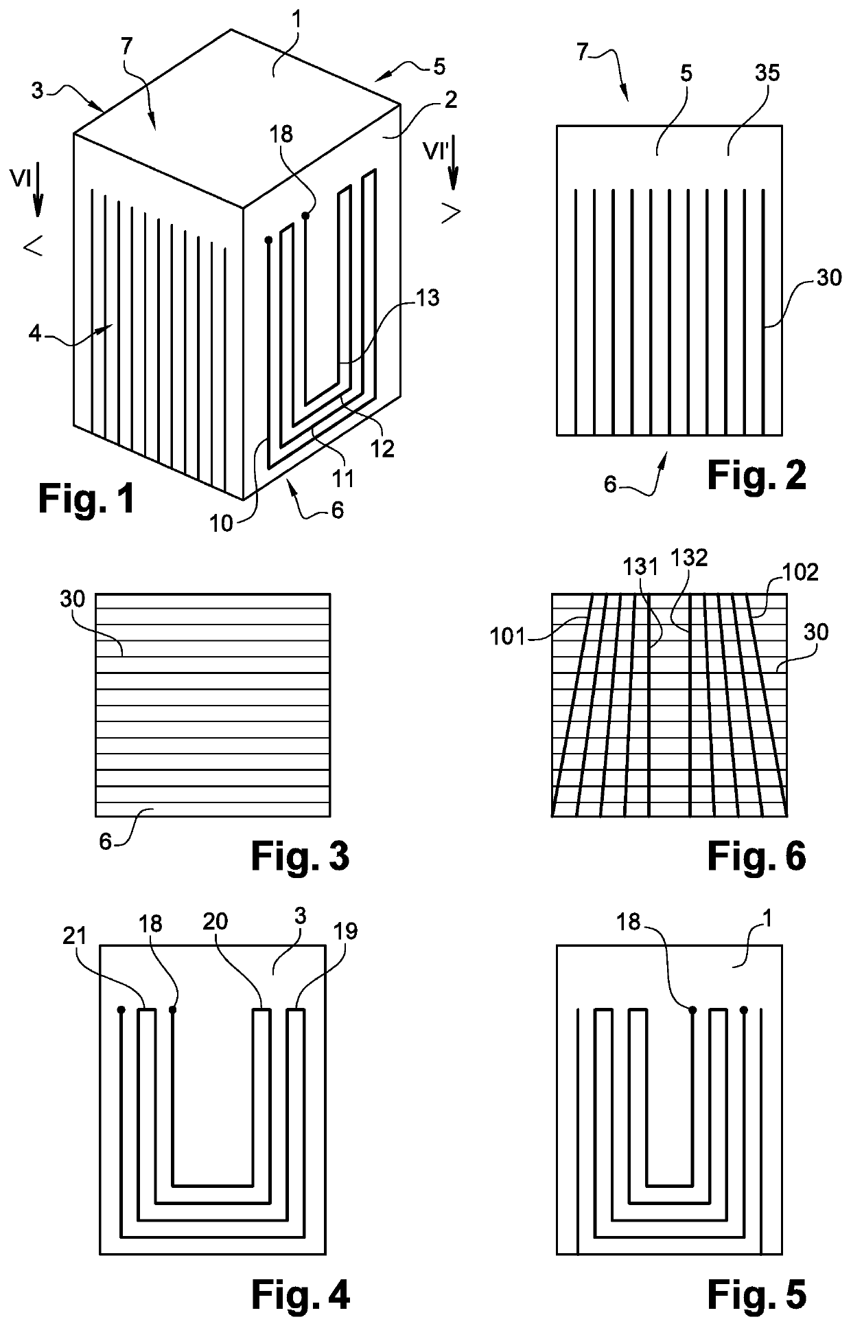
[0066]To execute this method, as shown very schematically in FIG. 1, a block of conductive material can be used, typically copper-based or equivalent, whose volume corresponds substantially to that of an elemental coil intended to be placed on a stator pole.

[0067]This block 1 is machined to produce a set of cuts that will define the elemental turns with which to make the part of the stator coil, which will be inserted inside the stator magnetic circuit.

[0068]More precisely, and as shown in FIG. 1, the block 1 comprises a surface 2, which, once the coil has been inserted in the stator, is intended to come into contact with the yoke of the stator. In the remainder of the description, this surface will be considered as the front surface of the block. Thus, the rear surface 3 is the one that will be intended to face the ...


PUM


Abstract

An electric motor stator includes a magnetic circuit having a plurality of radial polar protuberances. The stator has, for all or some of said protuberances, a set of conductive zones in the general shape of a U, disposed around the protuberance, and the ends of each of the conductive zones are located in the vicinity of a common plane. The stator also has at least one connection component including a plurality of conductive tracks connected to distinct ends of said conductive zones, so as to define a DC electric circuit forming a winding around one or more radial polar protuberances.

Description

TECHNICAL FIELD[0001]The present disclosure relates to the electrotechnical field, and more specifically that of rotary machines. More specifically, it targets a specific structure for motor stator coils, and also a production method with which to get advantages in terms of compactness and switching frequency of the supply circuit of the motor.BACKGROUND[0002]Typically, electric motors stators are composed of a magnetic circuit with a central opening intended to receive a rotor. This magnetic circuit comprises a peripheral yoke from which extend various radial protuberances forming stator poles directed towards the rotor. Each of these protuberances receives a coil intended to be supplied by one phase of a set of currents or voltages generating a rotating alternating field.[0003]Typically, the coils are made separately, by winding a wire onto a form having the shape of the stator pole. After production, these coils are inserted into the inner volume of the stator, and then placed on...

Claims


Application Information

Patent Timeline
Patent Type & Authority Applications(United States)
IPC IPC(8): H02K15/02H02K1/14
CPCH02K15/022H02K1/141H02K3/18H02K3/28H02K15/0068H02K15/0421H02K2203/09H02K15/0414H02K15/062
Inventor NOGAREDE, BERTRAND
Owner BNCE
Why Eureka
Try Eureka