
Improved coupling with pressure relief

a technology of pressure relief and coupling, which is applied in the direction of pipe couplings, functional valve types, couplings, etc., can solve the problems of increasing pressure, prone to surge pressure, damage to pumps, valves or other systems connected with the fluid system, etc., and achieves the effect of relieving surge pressure in the coupling

Active Publication Date: 2021-06-24
MANN TEKNIK
View PDF0 Cites 3 Cited by
  • Summary
  • Abstract
  • Description
  • Claims
  • Application Information

AI Technical Summary

Benefits of technology

The present invention is a valve assembly that helps relieve pressure surges during disconnection. It includes a coupling and an adapter, with a valve arranged in an annular body. The valve is biased in a first direction to seal against the valve seat, but will release fluid if the pressure acting on the valve exceeds a predetermined threshold. This helps prevent damage to equipment or personnel.

Problems solved by technology

However, such systems are prone to surge pressures.
The sudden reduction in fluid volume of the system leads to an increase in pressure.
This pressure can damage pumps, valves or other systems in connection with the fluid system.
However, such pressure relief valves require additional bores in the body of the coupling which add to the complexity of the coupling, and may furthermore release fluid directly towards the radial outside of the coupling, that is, towards a user.

Method used


Image

  • Improved coupling with pressure relief
  • Improved coupling with pressure relief
  • Improved coupling with pressure relief

Examples


Embodiment Construction

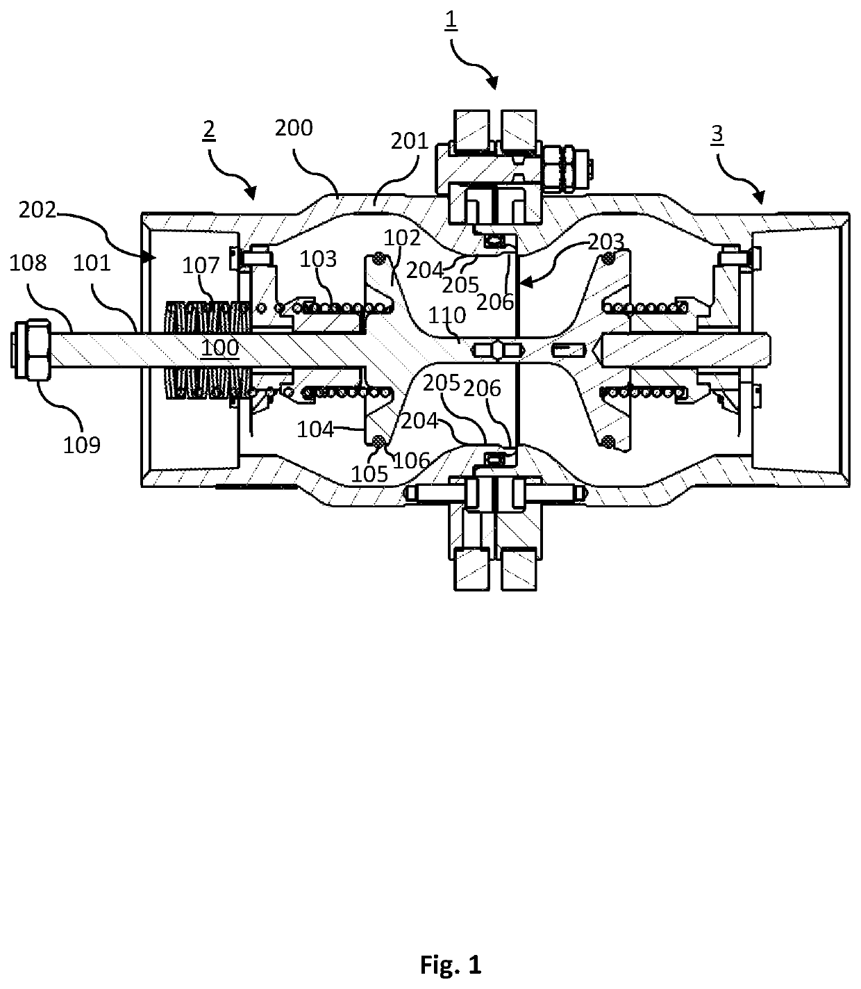
[0018]The leakage of a small volume of fluid has traditionally been avoided in for example break-away and dry disconnect systems. Break-away couplings could as described herein could for example be so called breaking pin couplings, cable release couplings, or PERC (powered emergency release coupling). The present inventors have, however, identified that a small volume of controlled leakage is acceptable when it means that other elements of a fluid transfer system such as pumps and other valves are not damaged. At disconnection of for example a break-away coupling the coupling 2 is released from the adapter 3 closing the path for the liquid. This sudden restriction stopping the flow momentarily creates a rapidly increasing pressure at the valve in the coupling 2.

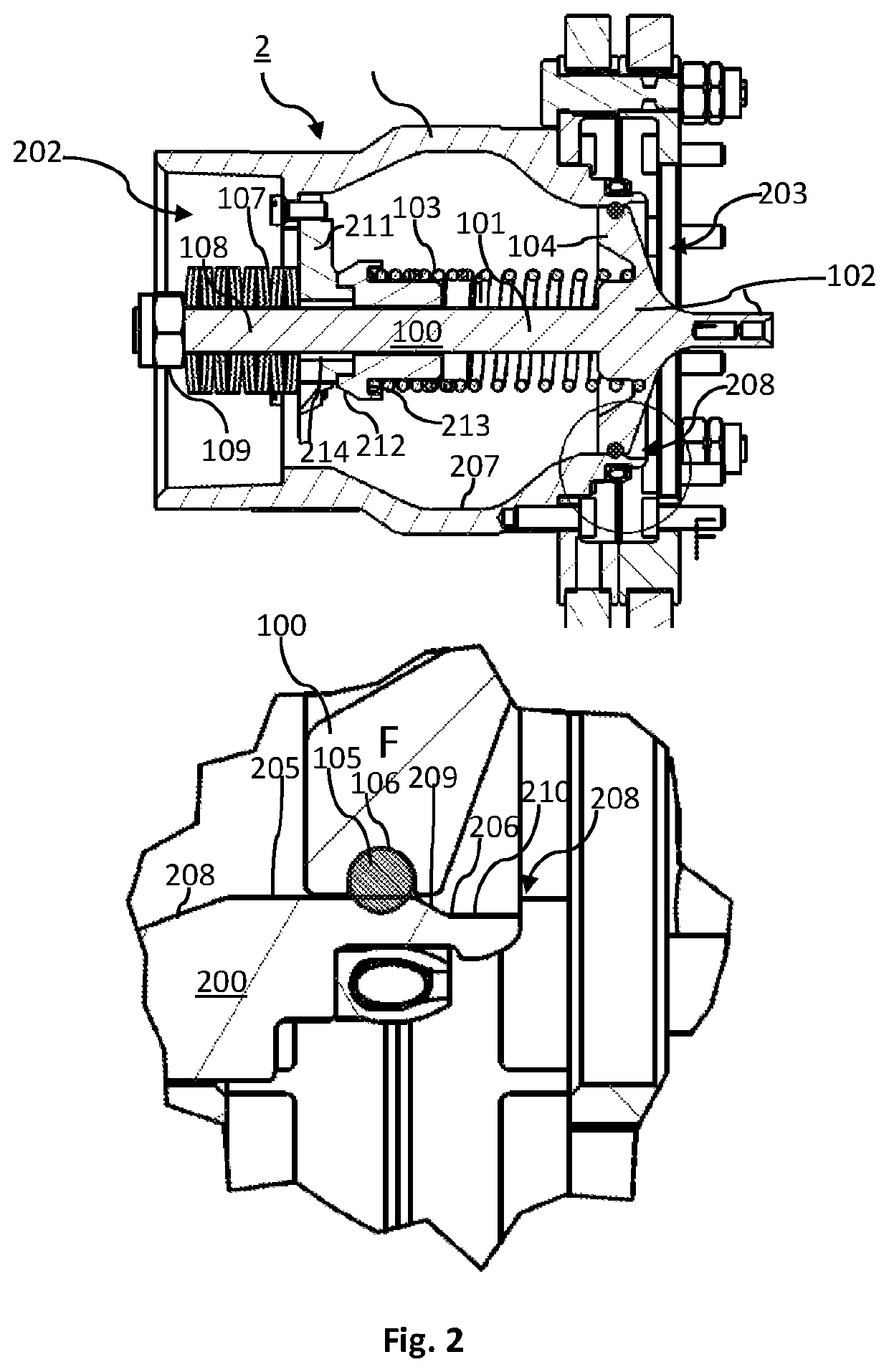
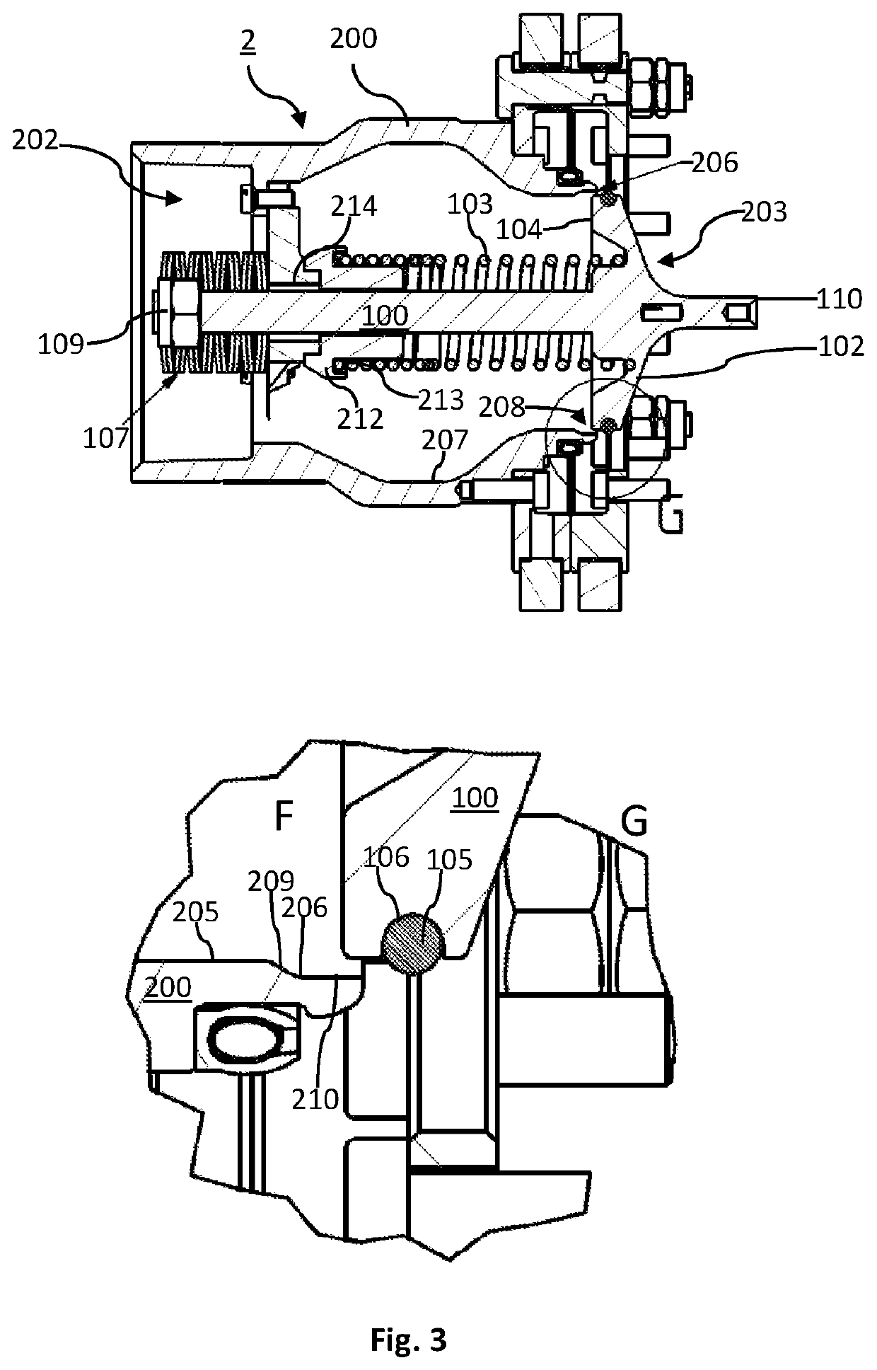
[0019]FIG. 1 shows a valve assembly 1 comprising a coupling 2 and an adapter 3. During operation, the valve assembly 1 forms a fluid conduit for the transfer of fluids. The valve assembly 1 may be a dry disconnect, or break-a...


PUM


Abstract

A coupling for a break-away valve assembly includes a coupling and an adapter, the coupling including: a valve arranged in an annular body, the annular body having a valve seat including a first portion and a second portion, adjacent to the first portion, of greater internal diameter relative to the first portion, the valve being biased in a first direction to seal against the valve seat on disconnection of the coupling from the adapter, wherein the valve is biased in a second direction, and the valve is adapted to extend past the first portion into the second portion of the valve seat to release a volume of fluid if the pressure acting on the valve exceeds a predetermined surge pressure threshold.

Description

FIELD OF THE INVENTION[0001]The present disclosure relates to coupling for break-away valve assemblies. In particular it relates to couplings for break-away valve assemblies comprising a valve biased in a first direction and a second direction.BACKGROUND OF THE INVENTION[0002]Fluid transfer systems are used to transfer a fluid from a source to a destination. Dry disconnect or break-away coupling assemblies are used in fluid transfer systems to provide dry couplings and break-away couplings. Break-away coupling assemblies generally comprise a first and second coupling half, herein described as a coupling and an adapter. A break-away coupling is adapted to facilitate a controlled breaking point between the coupling and adapter if the fluid transfer system is exerted to a force that otherwise would risk the fluid integrity of the fluid transfer system.[0003]To form a fluid conduit the coupling and the adapter are connected together. The connection of the coupling to the adapter actuate...

Claims


Application Information

Patent Timeline
IPC IPC(8): F16L55/10F16L29/04
CPCF16L55/1015F16L37/32F16L29/04F16L55/10F16K17/36F16K17/0466F16K17/044F16L2201/20F16L55/1007Y10T137/1654Y10T137/1662F16K2200/302
Inventor BÄCKSTRÖM, MARCUSADAMSSON, FREDRIK
Owner MANN TEKNIK
Learn More