An optical probe system

a technology of optical probes and probes, applied in the field of optical probe systems, to achieve the effects of improving optical probe systems, improving data transmission, and improving optical probe systems

Inactive Publication Date: 2015-11-26
KONINKLJIJKE PHILIPS NV
View PDF13 Cites 23 Cited by
  • Summary
  • Abstract
  • Description
  • Claims
  • Application Information

AI Technical Summary

Benefits of technology

[0014]It would be advantageous to achieve an improved optical probe system. It would also be desirable to enable an optical probe system working faster and / or more accurate, particularly with a higher data transmission and / or a relatively higher power provided at the distal end of the probe. In general, the invention preferably seeks to mitigate, alleviate or eliminate one or more of the above-mentioned disadvantages singly or in any combination. In particular, it may be seen as an object of the present invention to provide a system and a method that solves the above mentioned problems, or other problems, of the prior art. Other problems may be efficiency and / or high power density to allow for a small optoelectronic device at the tip of a catheter / probe so that the invasive medical device remains relatively thin and so that tissue heating is avoided and / or minimized as well.

Problems solved by technology

Other problems may be efficiency and / or high power density to allow for a small optoelectronic device at the tip of a catheter / probe so that the invasive medical device remains relatively thin and so that tissue heating is avoided and / or minimized as well.

Method used


Image

  • An optical probe system
  • An optical probe system
  • An optical probe system

Examples


Embodiment Construction

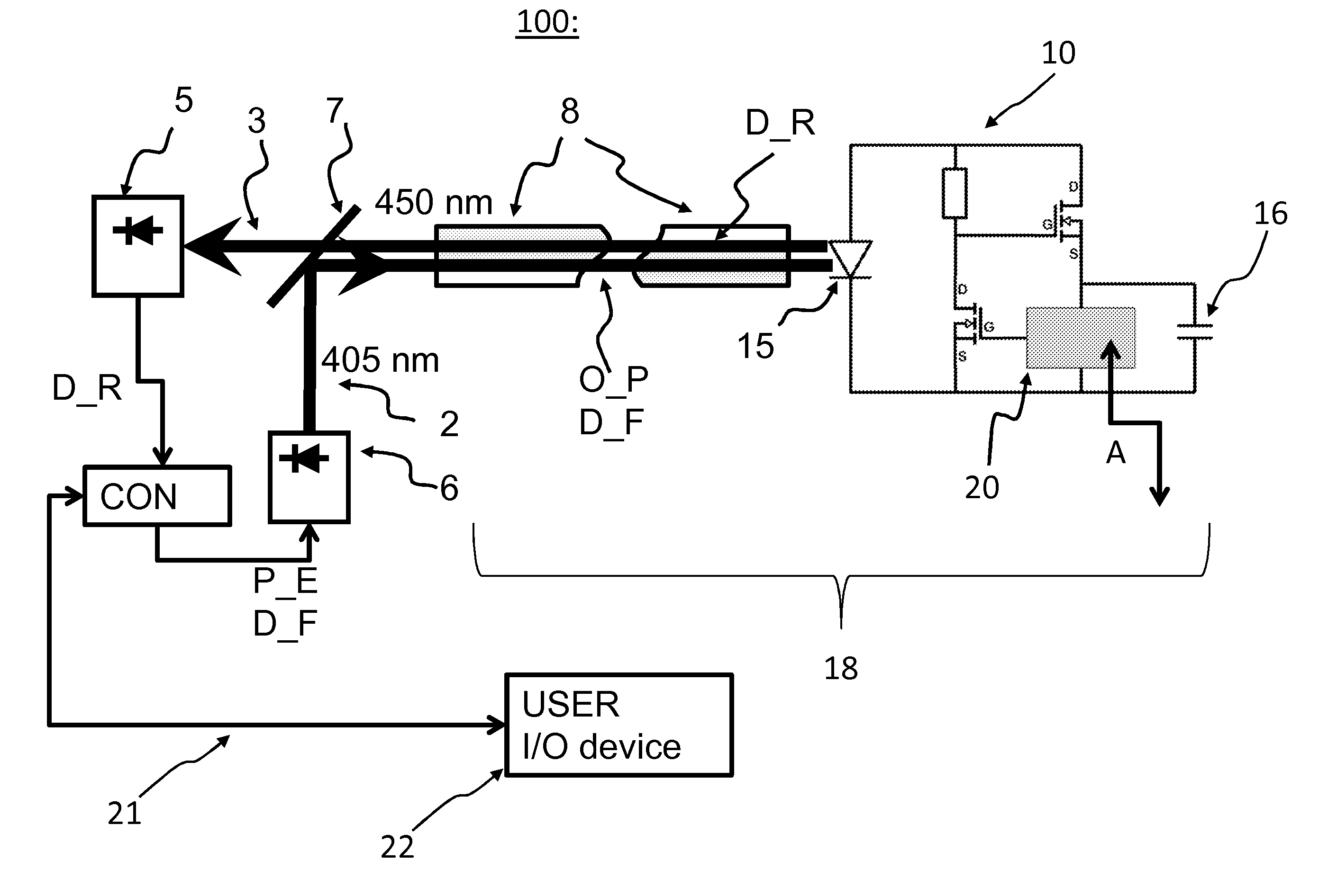
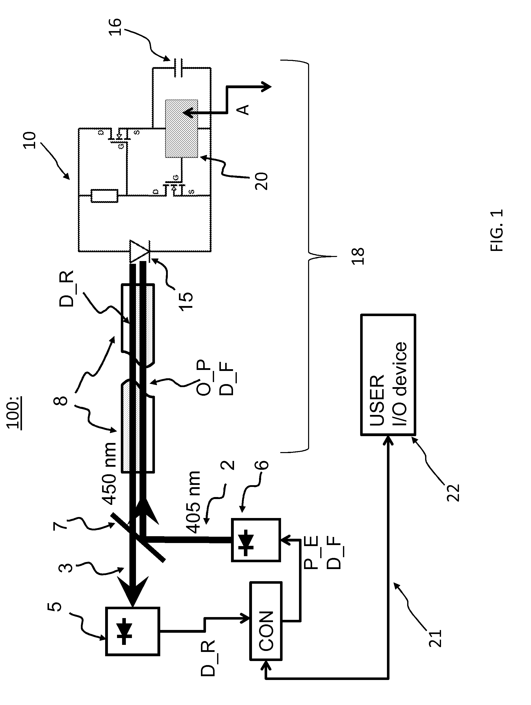
[0085]FIG. 1 shows a schematic embodiment of an optical probe system 100 according to the present invention.

[0086]A radiation source 6 is capable of emitting a first radiation beam, said first radiation beam 2 comprising optical energy O_P and first data D_F. A photodetector 5, the photodetector is arranged for detecting a second radiation beam 3.

[0087]An optical probe is, at its proximal end, optically connected to the photodetector and the radiation source, the probe having an optical guide 8, for example an optical fiber as schematically illustrated in FIG. 1, capable of connecting the distal end with the proximal end, the optical probe having at its distal end an optical converter circuit 10, the circuit comprising:

[0088]An application device 20, the application device being arranged for monitoring and / or manipulation, e.g. the influencing surrounding tissue of a human with acoustic or electromagnetic radiation, at the distal end of the probe, the application device being arrang...


PUM


Abstract

The present invention relates to an optical probe system (100) comprising an optical probe (18) having an optical converter circuit (10) with an optoelectronic device (15). The optoelectronic device is arranged for converting a first radiation beam (2) from a radiation source (6) into electrical energy and for receiving first data comprised in said first radiation beam. The optical converter circuit (10) is powerable by said electric energy in the first radiation beam (2). The optoelectronic device is further arranged for emitting a second radiation beam (3) towards a photodetector (5), said emission being inducible by the incoming first radiation beam, the second radiation beam comprising second data. The invention is advantageous for obtaining an improved optical probe system capable of obtaining a higher data transmission and/or a relatively high power at the distal end of the optical probe system with relatively high efficiency and simultaneous at small size.

Description

FIELD OF THE INVENTION[0001]The present invention relates to an optical probe system, and more particularly relates to an optical probe system comprising an optoelectronic device being arranged for converting a first radiation beam into electrical energy, the invention relates to a corresponding optical probe, and the invention further relates to a corresponding method.BACKGROUND OF THE INVENTION[0002]There is a clear and ongoing trend to replace conventional surgical procedures with minimally invasive (MI) interventions. Reduced trauma, shorter hospital stay and reduced cost are the most important drivers of the adoption of minimally invasive techniques.[0003]To enable further innovation in medical instrumentation—thus enabling more advanced and more challenging MI interventions—there is a need to integrate miniature sensors for in-body imaging and physiological measurement in instruments like catheters and guide wires.[0004]Data and power delivery to the tip of long and thin devic...

Claims


Application Information

Patent Timeline
Patent Type & Authority Applications(United States)
IPC IPC(8): A61B1/05A61B1/07A61B1/045A61B1/06A61B5/0205A61B5/1473A61B8/12A61B6/00A61B5/0402A61N1/36A61B1/00A61B5/03
CPCA61B1/051A61B5/01A61B1/07A61B1/045A61B1/00006A61B1/063A61B1/0684A61B5/036A61B5/1473A61B8/12A61B6/00A61B5/0402A61N1/36A61B5/02055A61B1/00126A61B5/6851A61B5/6852H04B10/40H04B10/807A61B1/005A61B1/00029A61B6/425A61B2560/0214H04B10/2589A61B5/301A61B5/318
Inventor VAN DER MARK, MARTINUS BERNARDUSVAN DUSSCHOTEN, ANNA HENDRIKA
Owner KONINKLJIJKE PHILIPS NV
Why Eureka
Try Eureka