Optical imaging lens

a technology of optical imaging and lens, applied in the field of optical imaging lenses, can solve the problems that the optical lens having both a miniaturized size and a desirable imaging quality cannot be manufactured, and achieve the effect of reducing the system length of the optical imaging lens and achieving the desired optical performan

Active Publication Date: 2021-06-24
GENIUS ELECTRONICS OPTICAL XIAMEN
View PDF4 Cites 0 Cited by
  • Summary
  • Abstract
  • Description
  • Claims
  • Application Information

AI Technical Summary

Benefits of technology

The invention is an optical imaging lens that solves the problem of distortion and allows for a larger view while keeping the lens's size reduced. This is achieved by designing the concave / convex shapes of the lens elements, which allows for better optical performance and reduces the impact of aberrations.

Problems solved by technology

However, when designing an optical imaging lens, an optical lens having both a miniaturized size and a desirable imaging quality cannot be manufactured by simply scaling down a lens with a desirable imaging quality.
Therefore, how to manufacture an optical imaging lens meeting the needs of consumer electronic products and facilitate the imaging quality of such optical lens has been an issue of this field.

Method used


Image

  • Optical imaging lens
  • Optical imaging lens
  • Optical imaging lens

Examples


first embodiment

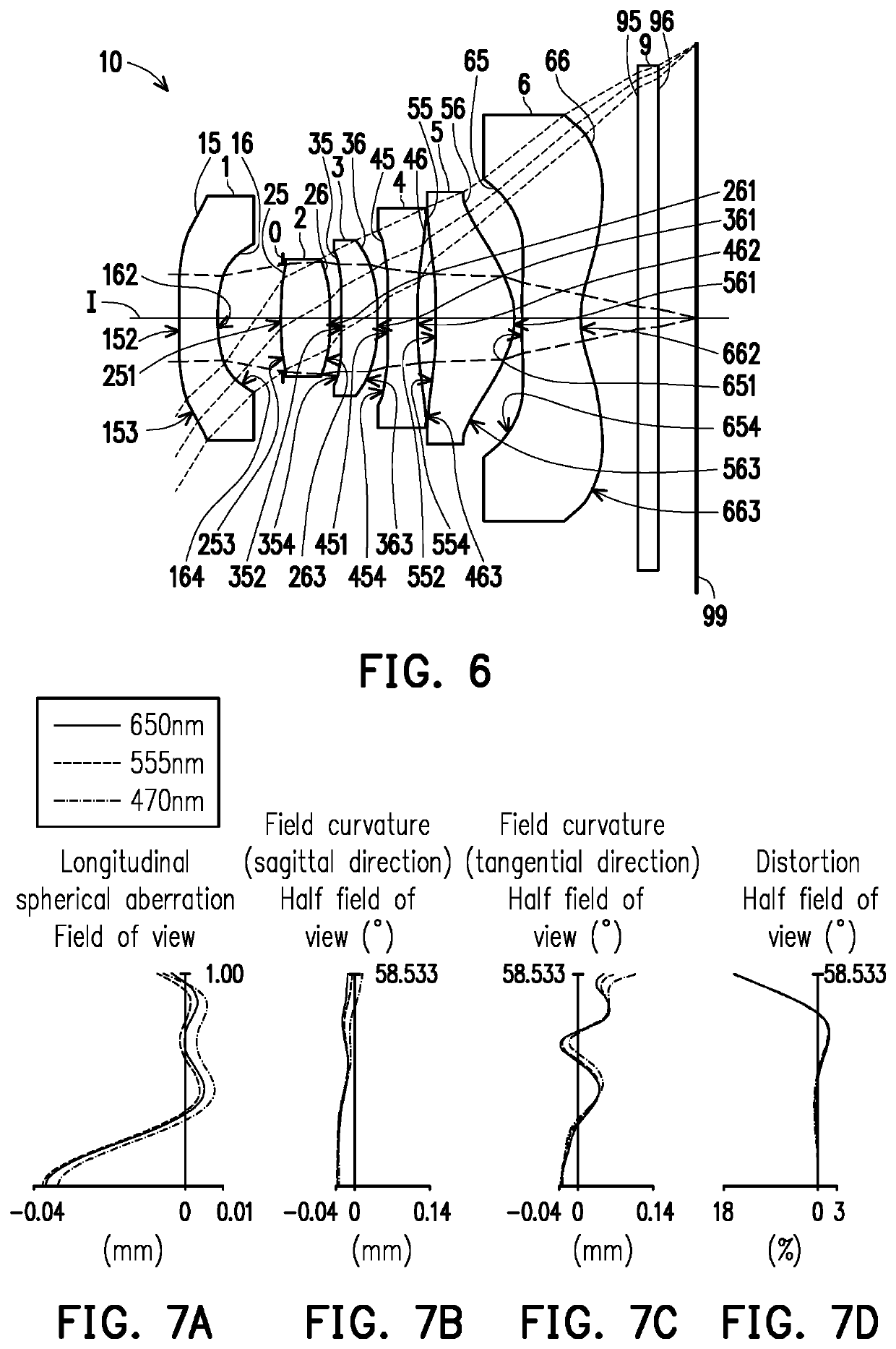
[0116]FIGS. 7B and 7C respectively illustrate the field curvature aberration in the sagittal direction and the field curvature aberration in the tangential direction on the image plane 99 when the wavelength is 650 mm, 555 mm, and 470 mm. In FIGS. 7B and 7C illustrating the field curvature aberrations, the field curvature aberrations of the three representing wavelengths in the whole field range fall within a range from −0.04 mm to 0.14 mm, indicating that the optical imaging lens of the first embodiment is able to effectively reduce aberration.

[0117]FIG. 7D illustrates the distortion aberration on the image plane 99 when the wavelength is 650 mm, 555 mm, and 470 mm. FIG. 7D illustrating the distortion aberration indicates that the distortion aberration is maintained within a range from −18% to 3%, indicating that the distortion aberration of the optical imaging lens of the first embodiment already satisfies the imaging quality requirement of an optical system.

[0118]Based on the abo...

second embodiment

[0120]Detailed optical data of the optical imaging lens 10 are as shown in FIG. 12. The system length (TTL) of the optical imaging lens 10 of the second embodiment is 4.865 mm, the effective focal length (EFL) thereof is 2.497 mm, the half field of view (HFOV) thereof is 58.439°, the image height thereof is 2.880 mm, and the f-number (Fno) thereof is 2.250.

[0121]Respective aspheric coefficients of the object-side surfaces and the image-side surfaces of the six lens elements of the second embodiment in Equation (1) are shown in FIG. 13.

[0122]In addition, relations of important parameters in the optical imaging lens 10 according to the second embodiment are as shown in FIGS. 42 and 43.

[0123]Referring to FIGS. 11A to 11D, in FIG. 11A illustrating the longitudinal spherical aberration, imaging point deviations of the off-axis rays in different heights are controlled within −0.02 mm to 0.14 mm when the pupil radius is 0.5548 mm. In FIGS. 11B and 11C illustrating the field curvature aberr...

third embodiment

[0126]Detailed optical data of the optical imaging lens 10 are as shown in FIG. 16. The system length (TTL) of the optical imaging lens 10 of the third embodiment is 5.600 mm, the effective focal length (EFL) thereof is 2.173 mm, the half field of view (HFOV) thereof is 58.459°, the image height thereof is 2.880 mm, and the f-number (Fno) thereof is 2.250.

[0127]Respective aspheric coefficients of the object-side surfaces and the image-side surfaces of the six lens elements of the third embodiment in Equation (1) are shown in FIG. 17.

[0128]In addition, relations of important parameters in the optical imaging lens 10 according to the third embodiment are as shown in FIGS. 42 and 43.

[0129]Referring to FIGS. 15A to 15D, in FIG. 15A illustrating the longitudinal spherical aberration, imaging point deviations of the off-axis rays in different heights are controlled within −0.045 mm to 0.025 mm when the pupil radius is 0.4828 mm. In FIGS. 15B and 15C illustrating the field curvature aberra...


PUM


Abstract

An optical imaging lens includes a first, a second, a third, a fourth, a fifth, and a sixth lens elements from an object side to an image side arranged in order along an optical axis. The six lens elements are the only lens elements having refracting power in the optical imaging lens. An optical axis region of an object-side surface of the third lens element is concave. A periphery region of an image-side surface of the fourth lens element is concave. An optical axis region of an image-side surface of the sixth lens element is concave.

Description

CROSS REFERENCE TO RELATED APPLICATION[0001]This application is a continuation application of and claims the priority benefit of U.S. application Ser. No. 16 / 015,191, filed on Jun. 22, 2018, now allowed. The prior U.S. application Ser. No. 16 / 015,191 claims the priority benefit of China application serial no. 201810294461.2, filed on Mar. 30, 2018. The entirety of each of the above-mentioned patent applications is hereby incorporated by reference herein and made a part of specification.BACKGROUND OF THE INVENTIONTechnical Field[0002]The invention relates to an optical imaging lens.Description of Related Art[0003]The specification of consumer electronic products is ever changing and the demand for lighter, thinner, and smaller products never stops growing, which is why the specification of key components (optical imaging lenses and etc.) of the electronic products must also continue to be enhanced, so as to satisfy consumers' demands. The most important features of the optical imagin...

Claims


Application Information

Patent Timeline
Patent Type & Authority Applications(United States)
IPC IPC(8): G02B9/62G02B13/00
CPCG02B9/62G02B13/0045G02B13/0015
Inventor CHEN, FENGYIN, YANXUANFAN, TA-CHENG
Owner GENIUS ELECTRONICS OPTICAL XIAMEN
Why Eureka
Try Eureka