Inhaler

a technology of inhaler and trigger mechanism, which is applied in the direction of inhalators, etc., can solve the problems of affecting the reliability of the inhaler, less robust trigger mechanism of the prior art inhaler, and more sensitive to manufacturing tolerances, so as to improve control, facilitate the movement of the rod, and facilitate the effect of dose dispensing

Pending Publication Date: 2021-07-01
ASTRAZENECA AB
View PDF21 Cites 0 Cited by
  • Summary
  • Abstract
  • Description
  • Claims
  • Application Information

AI Technical Summary

Benefits of technology

[0007]The claimed inhaler overcomes at least one of the drawbacks of the prior art. For example, an inhaler is provided in which a reduced number of components, compared with the prior art, form a trigger mechanism that reliably releases a canister drive for movement under a force from a loaded biasing means, to dispense a dose of medicament from a canister received within the canister drive. Having fewer components performing this function compared with the prior art not only improves manufacturing ease, time and costs, but also may be more reliable and robust than prior art arrangements, as there are fewer parts that might fail and / or be misassembled and tolerances are improved. Having the latch engage with the canister drive and with the blocker provides a simple mechanism with only two components forming the trigger mechanism in this arrangement, compared with the multiple components disclosed in the prior art, for example in WO 2013 / 038170, and optionally the components can be formed from relatively rigid and robust materials (e.g. moulded plastic), whereas the more complex trigger mechanisms of the prior art require multiple components made from many different materials, including one component comprising two very different materials (metal and plastic) that requires separate assembly before use.
[0025]Optionally the load-relieving mechanism is configured to release the moving component to thereby bring the rod of the damping system, under the load of the biasing means, into contact with the canister, when the canister is received in the inhaler body, such that the rod is enabled to apply the driving force to the canister to drive the canister from the rest position to at least the actuating position. Thus, the rod only contacts the canister when the biasing force is about to be applied to the canister and reduces the likelihood of wear of the rod when the inhaler is not about to be used. Optionally the load-relieving mechanism is configured such that the cam follower does not abut the edge of the cam track when the load-relieving mechanism is supporting the moving component and / or the part of the damping system. Again, this alleviates any stresses or wear that might otherwise occur, for example between the cam follower and the edge of the track.

Problems solved by technology

Therefore, it is possible that the trigger mechanism of the prior art inhaler may be less robust and more sensitive to manufacturing tolerances than is desirable and the reliability of the inhaler may be impacted as a result.

Method used


Image

  • Inhaler
  • Inhaler
  • Inhaler

Examples


Embodiment Construction

[0056]Inhalers and methods of operating inhalers in accordance with embodiments of the present invention are illustrated in the figures.

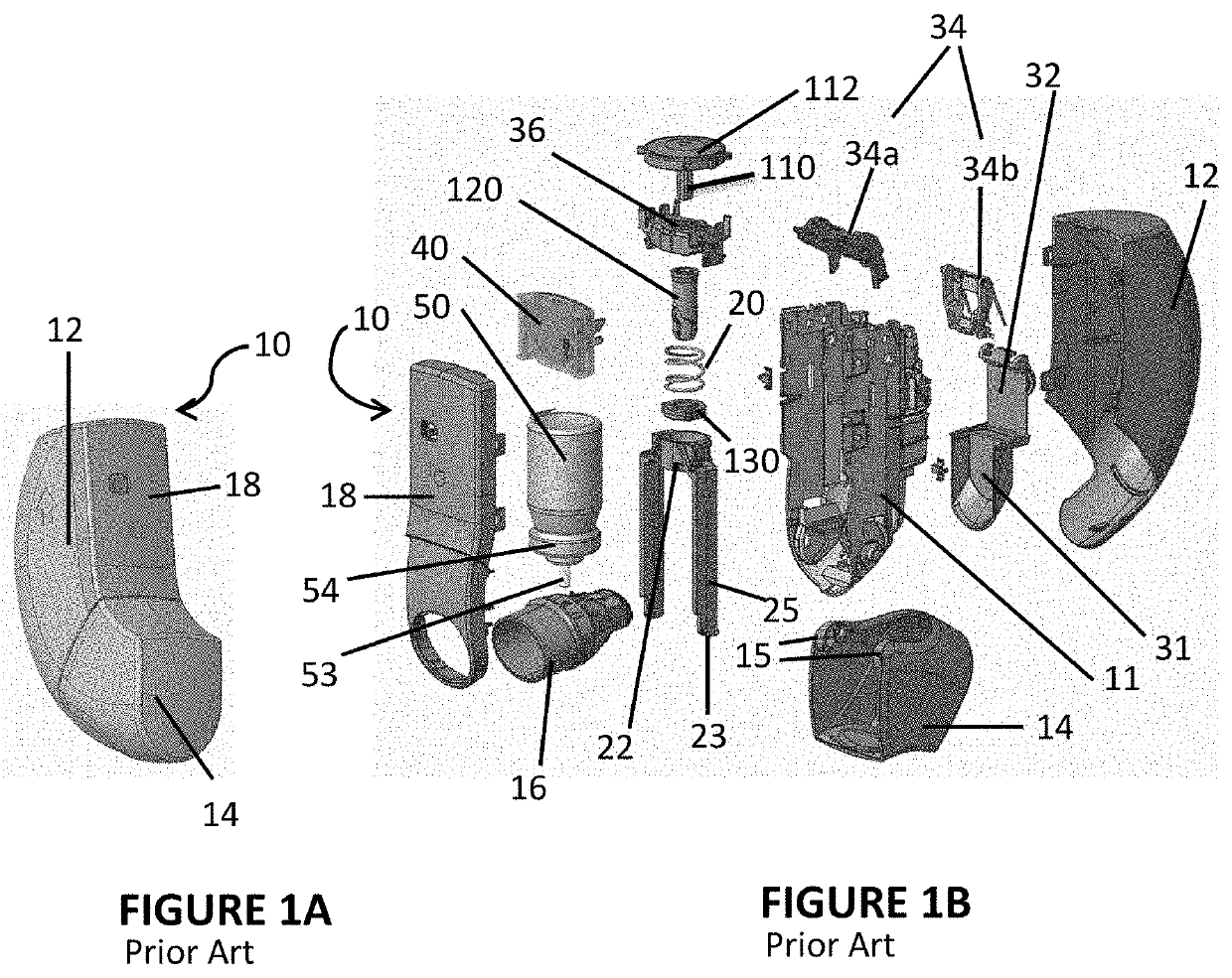
[0057]Referring to FIGS. 1A and 1B, an inhaler 10 is shown, which in this illustration is a breath-triggered inhaler 10 with a breath-triggering mechanism 32, 34. The inhaler 10 of FIGS. 1A and 1B is similar to the prior art inhaler of WO 2013 / 038170, but with additional components compared with this earlier publication for damping return of the canister 50.

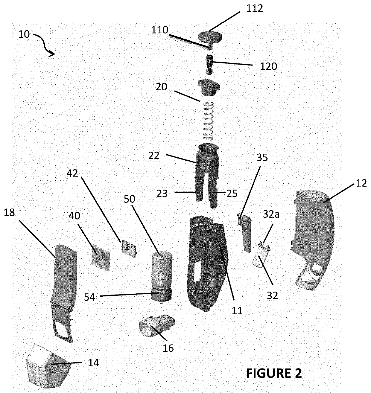
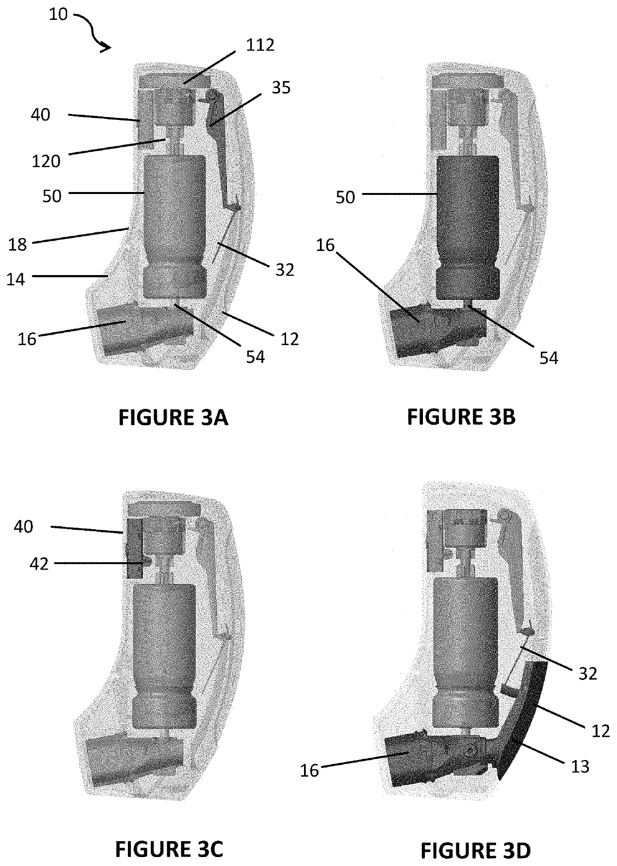
[0058]The inhaler 10 of FIGS. 1A and 1B has an outer housing or shell 12, which contains most of the components of the inhaler 10. At the base of the shell 12 there is a movable mouthpiece cover or cap 14 that pivots relative to the shell 12 to expose or cover the mouthpiece 16 of the inhaler 10. In combination with the front plate or fascia 18 of the inhaler 10, the shell 12 and cap 14 entirely enclose all the components of the inhaler 10 when in the closed configuration (as can be seen in FIG. ...


PUM


Abstract

There is disclosed an inhaler 10 for delivery of a medicament by inhalation. The inhaler 10 comprises a drive mechanism comprising a canister drive 22 for receiving a canister 50 of medicament, a biasing means 20, and a trigger mechanism. The trigger mechanism comprises a latch 35. The latch 35 has a locked position in which it contacts the canister drive 22 to prevent linear movement of the canister drive 22 and holds the biasing means 20 in a loaded configuration; and an unlocked position in which the latch 35 is disengaged from the canister drive 22 and releases the biasing means 20 from the loaded configuration to drive the canister drive 22 from a rest position to an actuated position. The trigger mechanism comprises a blocker 32. The blocker 32 has a blocking position in which it contacts the latch 35 to block movement thereof from the locked position to the unlocked position; and a rotated position in which the blocker 32 is disengaged from the latch 35 and allows movement of the latch 35 from the locked position to the unlocked position. The blocker 32 is rotatable in response to a force applied to the blocker 32. A method of operation of an inhaler 10 is also disclosed.

Description

TECHNICAL FIELD[0001]The present invention relates to an inhaler for delivery of a medicament by inhalation and methods of operation thereof, and in particular to the mechanisms of the inhaler for dispensing a dose of medicament and to the components for triggering dispensing of a dose and for controlling dispensing of a dose. The present invention also relates to a method of dispensing medicament from an inhaler, and in particular to a method of dispensing a dose of medicament from the inhaler.BACKGROUND OF THE INVENTION[0002]There are many ways to provide a dose of medicament to a patient or other intended recipient of the medicament, particularly when it is desired to provide multiple doses of the medicament, for example as part of a treatment regimen or otherwise. Many medicaments, such as those for treating pulmonary or other conditions, are delivered / dispensed to the recipient by inhalation using a suitable inhaler. One commonly used and effective type of multiple dose inhaler...

Claims


Application Information

Patent Timeline
Patent Type & Authority Applications(United States)
IPC IPC(8): A61M15/00
CPCA61M15/007A61M15/0081A61M15/0026A61M15/009A61M15/0091
Inventor DUCCE, RUNE
Owner ASTRAZENECA AB
Why Eureka
Try Eureka