
Stationary exercise apparatus for indoor cycling

a stationary exercise and indoor cycling technology, applied in the direction of sport apparatus, gymnastic exercise, cardiovascular exercise devices, etc., to achieve the effect of slim fram

Active Publication Date: 2021-07-08
WATOMIQ GMBH
View PDF0 Cites 0 Cited by
  • Summary
  • Abstract
  • Description
  • Claims
  • Application Information

AI Technical Summary

Benefits of technology

[0006]Flywheels are common in exercise bikes but the present inventor has realized that a flywheel with a radial gap in the periphery, preferably a centrally located radial gap, like two parallel flywheels with a gap there between, provides a number of advantages. I.e. in one embodiment the presently disclosed a stationary exercise bike comprises a lower frame housing a flywheel drivable by a rotatable crankshaft, the flywheel having a radial gap in the periphery.
[0007]A first advantage is that the gap makes it possible to insert a magnet into the gap of the flywheel. Hence, in a first embodiment of the presently disclosed exercise bike at least the periphery of the flywheel has conductive and / or ferromagnetic properties, and a magnetic resistance unit is configured to controllably insert one, two or more magnets into said radial gap in the flywheel. This has turned out to be a very efficient solution for providing a magnetic resistance of a flywheel and makes it possible to design a very slim frame for the exercise bike.
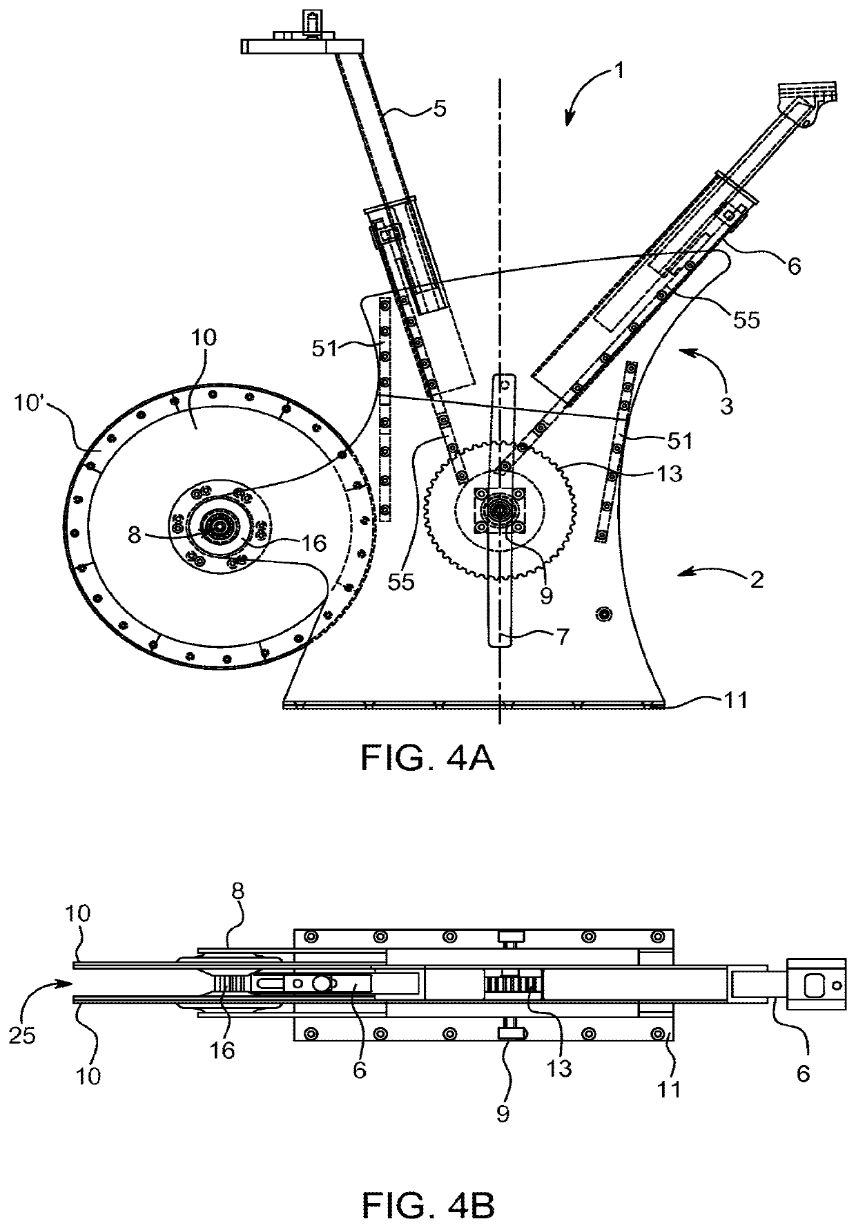
[0008]A second advantage of a radial gap is that the flywheel can be belt or chain driven centrally through this radial gap. Hence, in a further embodiment of the presently disclosed exercise bike the flywheel comprises a first driving wheel and the radial gap is extending to the first driving wheel. A driving unit having a second driving wheel can then be displaced from and parallel to the first driving wheel, and a driving element can further be provided to connect the first and second driving wheels through the radial gap in the flywheel. In that way the flywheel can be driven centrally, e.g. at the axis of the centre of mass of the flywheel.

Problems solved by technology

It is a challenge to simulate the feeling and flow of a normal bicycle in a stationary exercise bike, especially across a large power input from light pedalling to time trials and intensive sprints.
It is furthermore a challenge to provide a precise monitoring of the power input delivered to the exercise bicycle, because that is important in order to motivate the users.

Method used


Image

  • Stationary exercise apparatus for indoor cycling
  • Stationary exercise apparatus for indoor cycling
  • Stationary exercise apparatus for indoor cycling

Examples


example

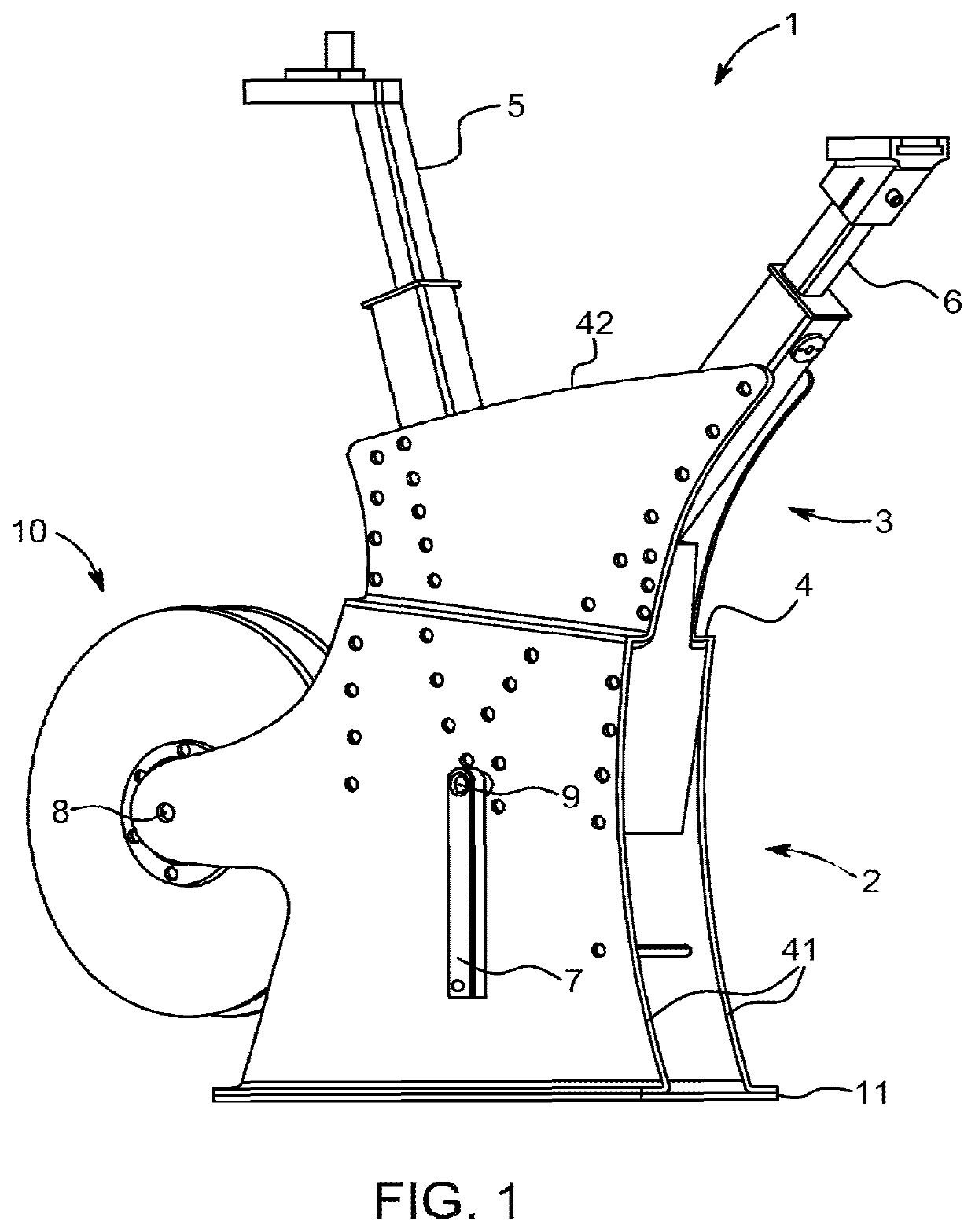
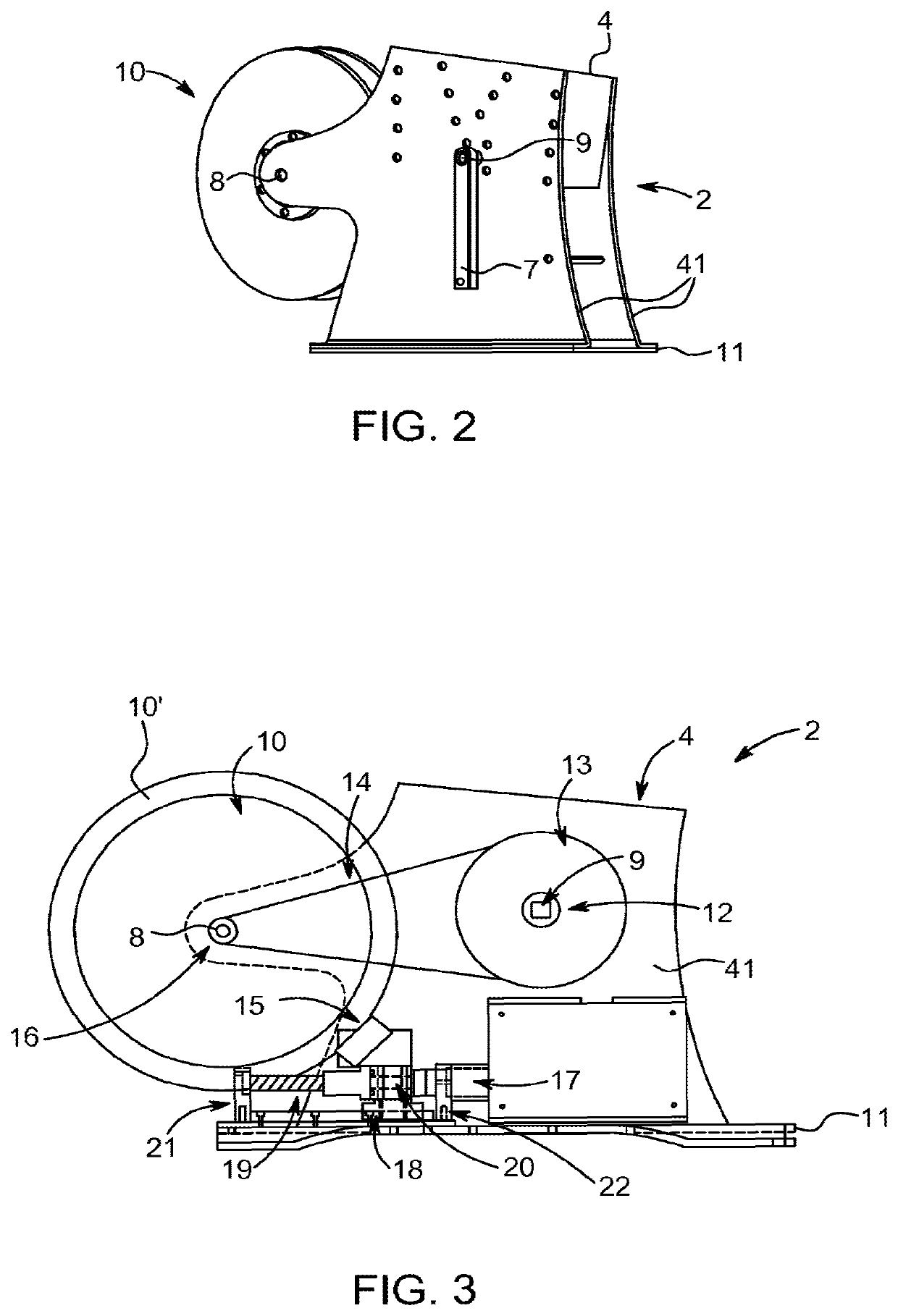
[0047]An exemplary stationary exercise bicycle 1 is illustrated in the drawings. The bike 1 comprises a lower frame 2 housing the flywheel 10 rotating on the flywheel shaft 8 and the crankshaft 9 having crankarms 7 thereon. The lower frame 2 rests on the bottom plateau 11. Attached to the separate lower frame 2 is the upper frame 3 housing the height adjustable seat tube 5 whereon a saddle can be mounted and the height adjustable head tube 6 whereon handlebars can be mounted. The lower frame 2 and the upper frame 3 can be separated at the point 4 as seen in FIG. 2 where the lower frame 2 is separately illustrated.

[0048]The flywheel 10 is formed by two parallel aluminium plates mounted on a flange 23 forming a radial gap 25 therebetween which is 40 mm wide. The diameter of the flywheel is 390 mm. The gap 25 between the plates makes it possible to have a toothed wheel with 16 teeth on the flywheel shaft centrally between the plates. The two parallel plates of the flywheel 10 are mount...


PUM


Abstract

The present disclosure relates to a stationary exercise apparatus for indoor cycle training (1), i.e. a stationary exercise bicycle, preferably provided with a magnetic resistance unit (15). One embodiment relates to a stationary exercise bike comprising a flywheel (10) defining a radial gap (25) in the periphery wherein at least the periphery of the flywheel (10) has ferromagnetic properties, and wherein a magnetic resistance unit (15) is configured to controllably insert one, two or more magnets into said radial gap.

Description

CROSS-REFERENCE TO RELATED PATENT APPLICATIONS[0001]The present application is a Continuation of application Ser. No. 15 / 754,127 filed Feb. 21, 2018 which is the National Stage of International Patent Application No. PCT / EP2016 / 070089, filed Aug. 25, 2016, which claims priority to Danish Patent Application No. PA 2015 00503, filed on Aug. 25, 2015, the disclosures of which are each incorporated herein by reference in their entirety.FIELD OF INVENTION[0002]The present disclosure relates to a stationary exercise apparatus for indoor cycle training, i.e. a stationary exercise bicycle, preferably provided with a magnetic resistance unit.BACKGROUND OF INVENTION[0003]Stationary exercise bicycles are known in the art. An exercise bike usually includes a frame for housing a rotatable element and a resistance unit, a handlebar mounted at a front end of the frame, a seat mounted at a rear end of the frame and a pair of crankarms with pedals. A display may also be provided for presenting infor...

Claims


Application Information

Patent Timeline
Patent Type & Authority Applications(United States)
IPC IPC(8): A63B21/005A63B22/00A63B22/06A63B24/00A63B71/06A63B21/22
CPCA63B21/0051A63B22/0046A63B22/0605A63B21/151A63B71/0622A63B21/225A63B24/0087A63B21/157A63B2024/0093A63B2220/10A63B2220/17A63B2225/09A63B2225/093A63B2220/78A63B21/00069
Inventor ANDERSEN, NIELS KRISTIAN SKOV
Owner WATOMIQ GMBH
Learn More