
Constant current circuit and semiconductor apparatus

semiconductor technology, applied in the direction of power conversion systems, dc-dc conversion, instruments, etc., can solve the problem that the temperature dependence of a constant current circuit or a constant current source may often become a problem

Active Publication Date: 2021-07-08
WINBOND ELECTRONICS CORP
View PDF0 Cites 1 Cited by
  • Summary
  • Abstract
  • Description
  • Claims
  • Application Information

AI Technical Summary

Benefits of technology

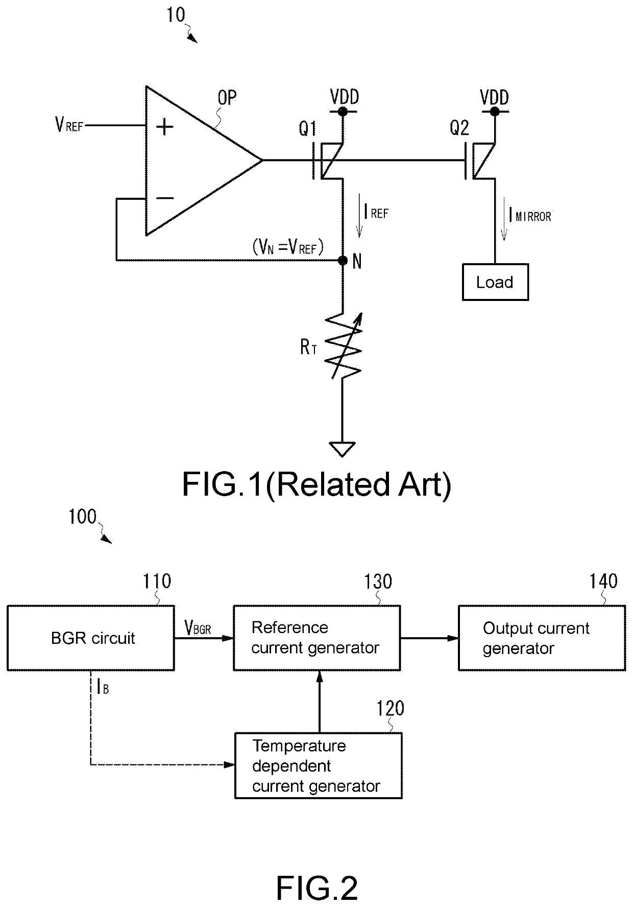
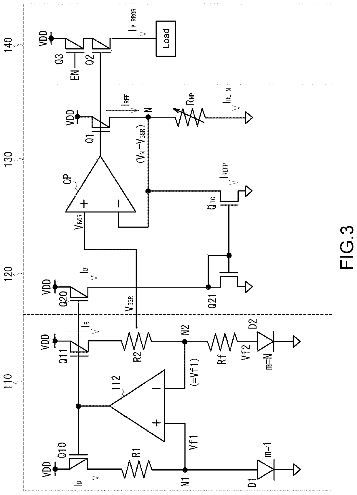
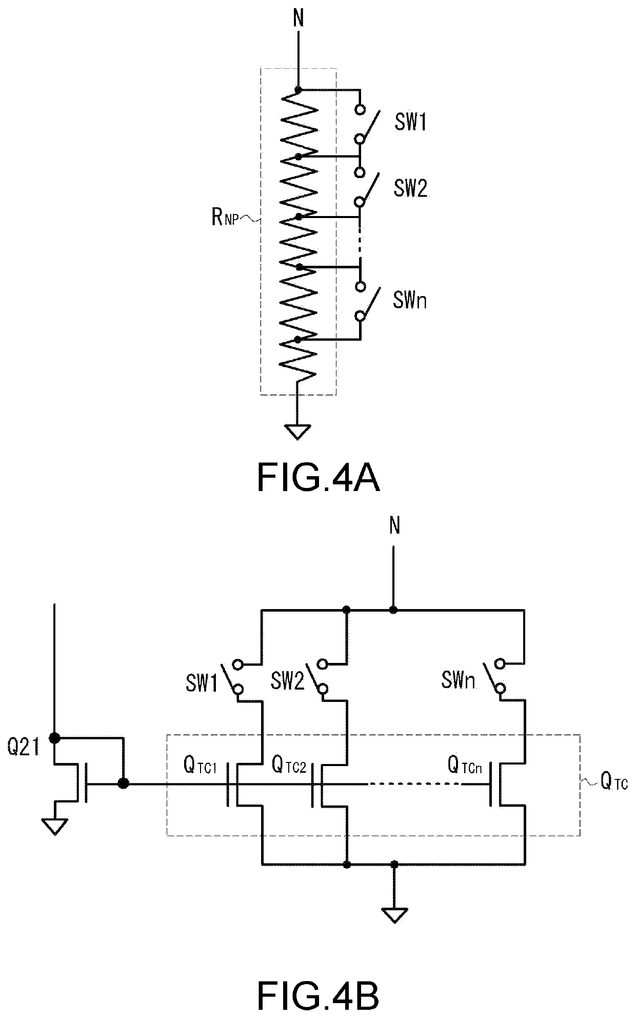
[0008]In one embodiment of the constant current circuit of the disclosure, the first circuit includes a unity gain buffer operating so as to generate the reference voltage at an output node and a resistor connected to a first path between the output node and ground. The reference current having the negative temperature coefficient is generated in the first path. The second circuit includes a second path connected in parallel with the first path. The reference current having the positive temperature coefficient is generated in the second path. The reference current is generated by adding up the reference current having the negative temperature coefficient and flowing through the first path and the reference current having the positive temperature coefficient and flowing through the second path. In one embodiment of the constant current circuit of the disclosure, the unity gain buffer is an operational amplifier including an inverting input terminal to which the reference voltage is input and a non-inverting input terminal in which the output node is short-circuited. The second circuit includes a first transistor of N-channel metal oxide semiconductor (NMOS) type generating the reference current having the positive temperature coefficient in the second path. In one embodiment of the constant current circuit of the disclosure, the first circuit includes a first adjustment circuit adjusting a magnitude of the reference current having the negative temperature coefficient. In one embodiment of the constant current circuit of the disclosure, the first adjustment circuit adjusts a resistance value of the resistor on the first path. In one embodiment of the constant current circuit of the disclosure, the second circuit includes a second adjustment circuit adjusting a magnitude of the reference current having the positive temperature coefficient. In one embodiment of the constant current circuit of the disclosure, the second adjustment circuit adjusts a drain curre...

Problems solved by technology

In design of an analog circuit, the temperature dependence of a const...

Method used


Image

  • Constant current circuit and semiconductor apparatus
  • Constant current circuit and semiconductor apparatus
  • Constant current circuit and semiconductor apparatus

Examples


embodiments

[0015]Next, a constant current circuit according to an embodiment of the disclosure will be described with reference to the drawings. FIG. 2 is a block diagram showing a configuration of a constant current circuit according to the present embodiment. FIG. 3 shows a circuit configuration of a constant current circuit. A constant current circuit 100 of the present embodiment includes a bandgap reference circuit (hereinafter “BGR circuit”) 110, a temperature dependent current generator 120, a reference current generator 130, and an output current generator 140. The BGR circuit 110 generates a reference voltage VBGR with low dependence on power supply voltage variations or temperature changes. The temperature dependent current generator 120 generates a temperature dependent current having a positive temperature coefficient. The reference current generator 130 generates a temperature-compensated reference current (or constant current) IREF by using the reference voltage VBGR and the temp...


PUM


Abstract

Provided is a constant current circuit supplying a temperature-compensated constant current. The constant current circuit includes a BGR circuit, a temperature dependent current generator, a reference current generator, and an output current generator. The BGR circuit generates a reference voltage with low voltage dependence. The temperature dependent current generator generates a temperature dependent current having a positive temperature coefficient. The reference current generator generates a temperature-compensated reference current by using the reference voltage and the temperature dependent current. The output current generator generates an output current based on the reference current generated by the reference current generator.

Description

CROSS-REFERENCE TO RELATED APPLICATION[0001]This application claims the priority benefit of Japan application serial no. 2020-000622, filed on Jan. 7, 2020. The entirety of the above-mentioned patent application is hereby incorporated by reference herein and made a part of this specification.BACKGROUNDTechnical Field[0002]The disclosure relates to a constant current circuit that supplies a constant current, and particularly to a constant current circuit that can be used as a constant current source for a semiconductor apparatus or the like.Description of Related Art[0003]There has been conventionally known a current mirror circuit for use in a constant current circuit, and such a constant current circuit is disclosed in, for example, Japanese Patent Laid-Open No. 2005-234890. In addition, a constant current circuit that outputs a constant current without being dependent on power supply voltage is disclosed in, for example, Japanese Patent Laid-Open No. 2013-97751.[0004]FIG. 1 shows ...

Claims


Application Information

Patent Timeline
IPC IPC(8): H02M3/155H02M1/32
CPCH02M3/155H02M2001/327H02M1/32G05F1/56G05F1/561G05F3/30G05F3/262G05F3/24G05F1/10G05F3/26
Inventor NAKATANI, MASAFUMI
Owner WINBOND ELECTRONICS CORP
Learn More