Rough cast blading with modified trailing edge geometry

Active Publication Date: 2021-07-15
SN DETUDE & DE CONSTR DE MOTEURS DAVIATION S N E C M A
View PDF0 Cites 0 Cited by
  • Summary
  • Abstract
  • Description
  • Claims
  • Application Information

AI Technical Summary

Benefits of technology

[0008]The present invention therefore aims at overcoming the drawbacks related to the deformation of the trailing edge during the polishing of the trailing edge by proposing a modificatio

Problems solved by technology

Given the thinness of the desired aerodynamic profile, this casting technique alone does not allow obtaining blading with a thin trailing edge and an additional subsequent polishing step is therefore used to mechanically adjust the trailing edge and thus be able to thin it.
Unfortunately, it appeared that such an additional material removal step to the rough cast blade did not allow complying with

Method used


Image

  • Rough cast blading with modified trailing edge geometry

Examples


Embodiment Construction

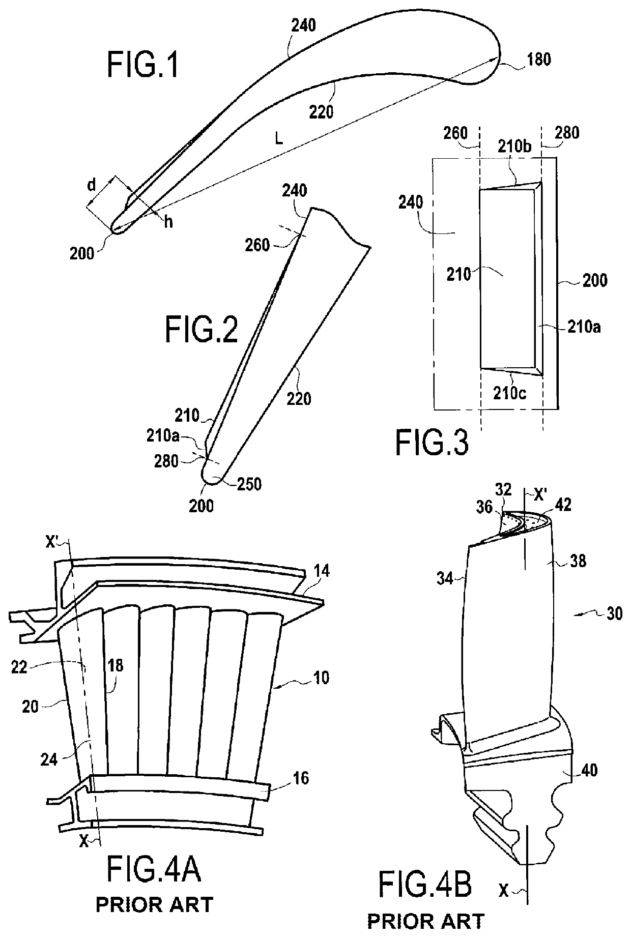
[0026]FIGS. 1 and 2 represent an aerodynamic profile or airfoil of a rough cast blading intended to form a turbine blade including a leading edge 18 and a trailing edge 20 opposite each other and connected by a pressure sidewall 22 and a suction sidewall 24 extending between a blade root and a blade tip. For the clarity of the description which follows, the elements of the rough cast blading have the same numbers as those of the finished blade to within a factor of 10. Thus, a leading edge of the rough blading 180 corresponds to the leading edge of the finished blade 18, a trailing edge of the rough blading 200 corresponds to the trailing edge of the finished blade 20, a pressure sidewall of the rough blading 220 corresponds to the pressure sidewall of the finished blade 22 and a suction sidewall of the rough blading 240 corresponds to the suction sidewall of the finished blade 24.

[0027]In accordance with the invention, in order to allow the production on the finished blade of a thi...


PUM

PropertyMeasurementUnit
Fractionaaaaaaaaaa
Angleaaaaaaaaaa
Angleaaaaaaaaaa

Abstract

A rough cast blading of this blade includes, a suction sidewall and/or a pressure sidewall of this blading intended to respectively form the suction sidewall and/or the pressure sidewall of the blade, a casting allowance extending over a determined width from a trailing edge of the blading intended to form the trailing edge of the blade in the direction of a leading edge of the blading intended to form the leading edge of the blade, except for a reserved area adjacent to the trailing edge of the blading and whose width is at least one radius of the trailing edge of the blading, over at least part of the height of the blading.

Description

BACKGROUND OF THE INVENTION[0001]The present invention relates to the general field of turbomachine turbine blading, and more particularly to the rough cast blading of turbine blades produced by the lost-wax casting technique.[0002]In a manner known per se, a turbomachine includes a combustion chamber in which air and fuel are mixed before being burned therein. The gases derived from this combustion flow downstream of the combustion chamber and then supply a high-pressure turbine and a low-pressure turbine. Each turbine includes one or more rows of vanes (called diffusers) alternating with one or more rows of blades (called movable wheels), spaced circumferentially all around the rotor of the turbine.[0003]FIG. 4A partly illustrates a conventional structure of diffusers currently fitted to numerous aircraft engines and including a plurality of vanes.[0004]Each of these vanes 10 includes an aerodynamic profile or an airfoil inserted between an outer platform 14 joining the vane tips ...

Claims


Application Information

Patent Timeline
IPC IPC(8): F01D5/14B22C7/02B22D25/02
CPCF01D5/141B22C7/02F05D2240/30F05D2220/32F05D2230/21B22D25/02F01D5/14B22C9/10
Inventor GIMEL, ALEXANDREBASSERY, JOSSERAND JACQUES ANDRÉGIVERT, MAXIME PAUL NUMAMIHAILA, GABRIELASOISSON, MARCTANG, BA-PHUC
Owner SN DETUDE & DE CONSTR DE MOTEURS DAVIATION S N E C M A
Why Eureka
Try Eureka