Turbo Charger Unit With Bearings For A Rotor Shaft

Inactive Publication Date: 2007-09-20
VOLVO LASTVAGNAR AB
View PDF13 Cites 9 Cited by
  • Summary
  • Abstract
  • Description
  • Claims
  • Application Information

AI Technical Summary

Benefits of technology

[0005] It is desirable to produce a shaft mounting for a turbocharger unit, which allows simple adjustment of a desired bearing pre-load without risk of deformation of bearing elements.

Problems solved by technology

If axial play is present in the mounting of the rotor shaft, the bearing life is adversely affected and there is also a risk of damage to the bearings.
This force must not be too large, however, since there is risk of deformation of the inner rings.
This high axial force can be unsuitably high, however, for the bearing inner rings.

Method used


Image

  • Turbo Charger Unit With Bearings For A Rotor Shaft
  • Turbo Charger Unit With Bearings For A Rotor Shaft
  • Turbo Charger Unit With Bearings For A Rotor Shaft

Examples


Embodiment Construction

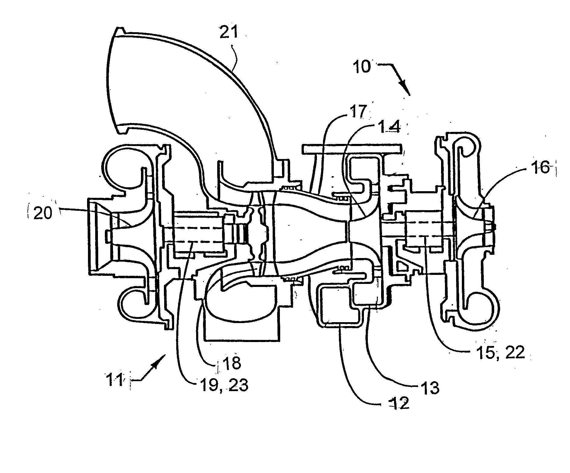
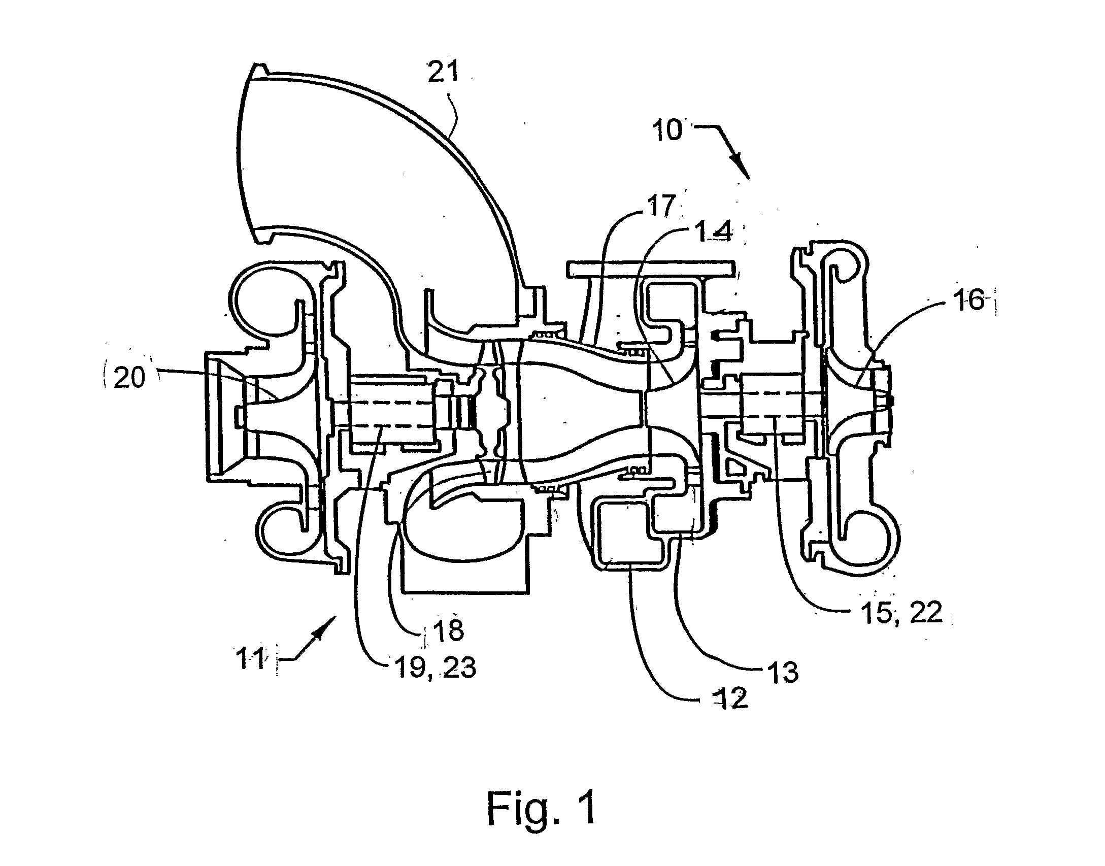
[0011] The shaft mounting according to the invention is shown in FIG. 1 applied to a two-stage turbocharger unit, but can also be used on a conventional single-stage turbo unit.

[0012] The first stage of the turbocharger unit is constituted by a high-pressure turbo unit 10, which cooperates with a series-connected low-pressure turbo unit 11. Exhaust gases are conducted from an internal combustion engine (not shown), for example a diesel engine, via separate pipe lines and worm-shaped turbine inlets 12, 13, into the turbine wheel 14 of the high-pressure turbo unit, which turbine wheel is mounted on a common shaft 15 with a compressor wheel 16. The exhaust gases are conducted onward via a pipe line 17 to the turbine wheel 18 of the low-pressure turbo unit 11, which mounted on a common shaft 19 with a compressor wheel 20. The exhaust gases are then conducted onward via a pipe line 21 to the exhaust system of the engine.

[0013] Filtered inlet air to the engine is conducted to the compre...


PUM


Abstract

A turbocharger unit has a shaft mounting for a rotor shaft. The shaft supports at one end a turbine wheel and at its other end a compressor wheel. The shaft is supported in a bearing housing by two axially spaced bearing elements, one of which forms an axial support via a shoulder on the shaft. A desired exact bearing pre-load is attainable if a discharger ring is mounted on the shaft by a threaded joint in such a way that the ring forms an axial support acting in the opposite axial direction against the other bearing element.

Description

BACKGROUND AND SUMMARY [0001] The present invention relates to a shaft mounting for a rotor shaft belonging to a turbocharger unit, which rotor shaft at its one end supports a turbine wheel and at its other end supports a compressor wheel and is supported in a bearing housing by means of two axially spaced bearing elements, one of which forms an axial support via a shoulder on the shaft. [0002] A turbocharger unit can operate at rotation speeds up to around 200,000 r.p.m. The mounting of the rotor of a turbo unit consists either of slide bearings, ball bearings or a combination of the two. Ball bearings produce the lowest power loss. The ball bearing application generally consists of two angular contact bearings, facing each other in a so-called O-arrangement (back-to-back arrangement). The two bearings can have a common outer ring with two elongated, separate inner rings, but can also consist of two normal angular contact bearings fitted in an outer sleeve and with a spacer sleeve ...

Claims


Application Information

Patent Timeline
IPC IPC(8): F02D23/00
CPCF01D25/16F16C19/54F16C25/06F16C2360/24F05D2240/50F05D2220/40F05D2240/52F16C19/163F16C19/548
Inventor GISELMO, KENTAUGUSTINSON, JONAS
Owner VOLVO LASTVAGNAR AB
Why Eureka
Try Eureka