Single use gear reduction device

Active Publication Date: 2021-07-15
ECA MEDICAL INSTR
View PDF0 Cites 0 Cited by
  • Summary
  • Abstract
  • Description
  • Claims
  • Application Information

AI Technical Summary

Benefits of technology

[0004]Many rotational tools (e.g. drills) operate at very high velocities, and it is sometimes necessary to reduce or limit how fast such tools spin. In the medical field, torque limiting devices in

Problems solved by technology

Many rotational tools (e.g. drills) operate at very high velocities, and it is sometimes necessary to reduce or limit how

Method used


Image

  • Single use gear reduction device
  • Single use gear reduction device
  • Single use gear reduction device

Examples


Example

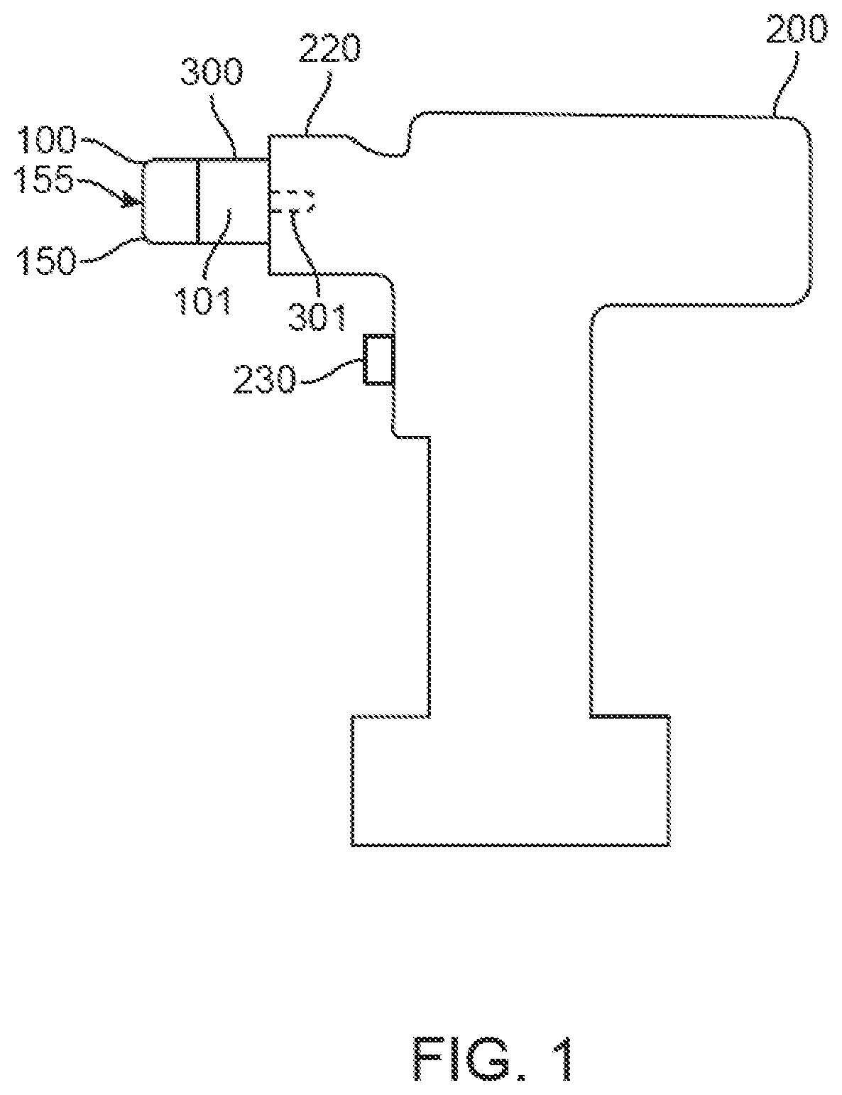
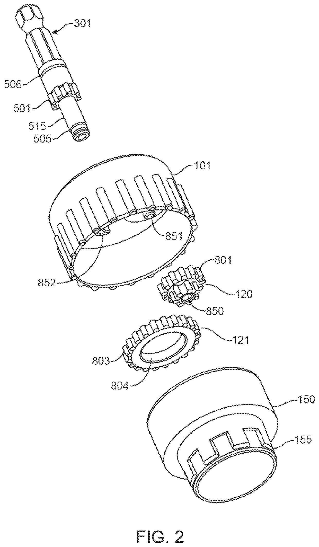
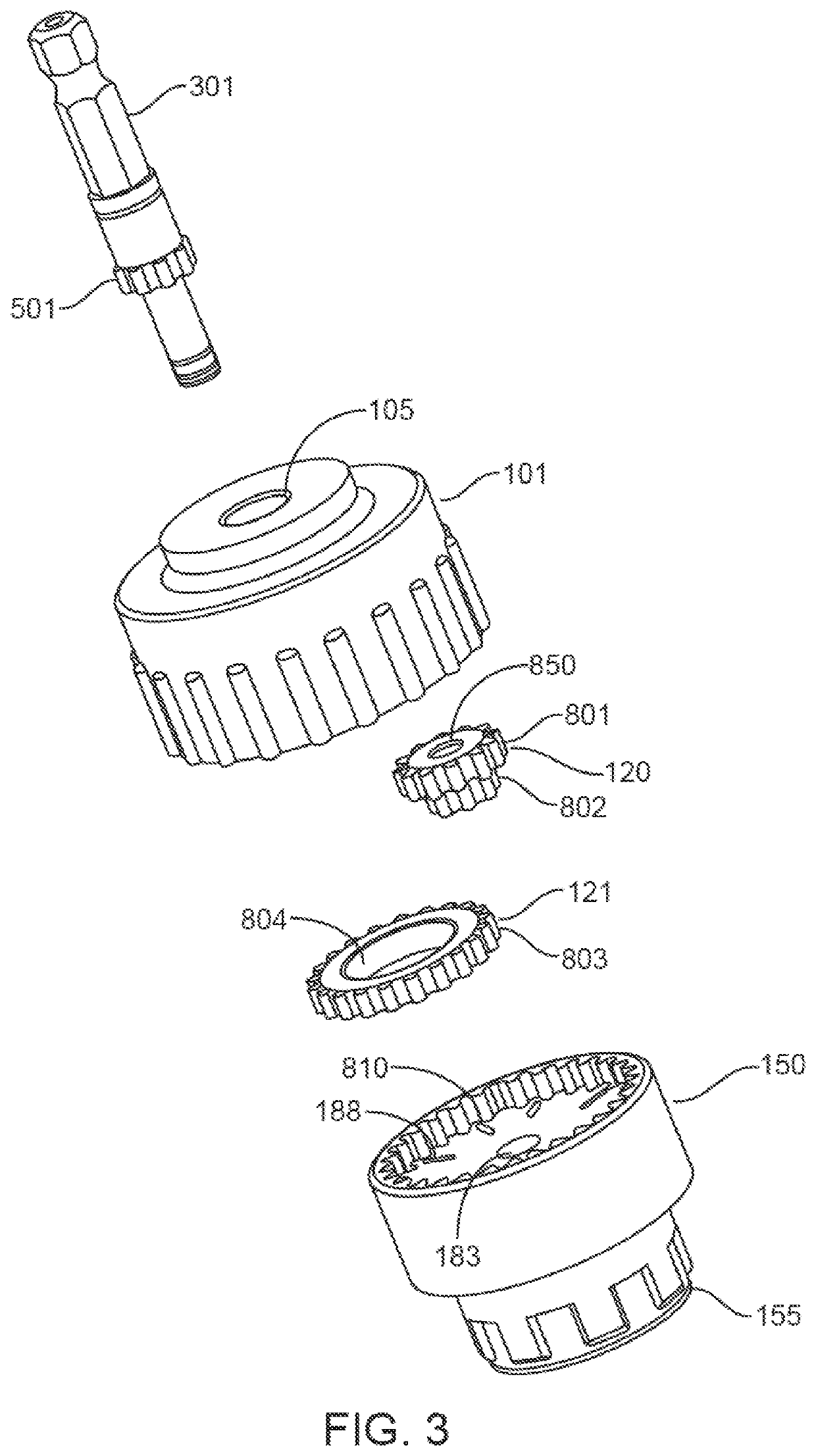
[0018]All reference numerals, designators, and call-outs in the figures are hereby incorporated by this reference as fully set forth herein. The failure to number an element in a figure is not intended to waive any rights, and unnumbered references may also be identified by alpha characters in the figures.

FURTHER DISCLOSURE

[0019]Some aspects of the disclosure will now be described in further detail with reference to the drawings, wherein like reference numbers refer to like elements throughout, unless specified otherwise. Certain terminology is used in the following description for convenience only and is not limiting.

[0020]For the purpose of illustrating the subject matter, there are shown in the drawings exemplary implementations of the subject matter; however, the presently disclosed subject matter is not limited to the specific methods, devices, and systems disclosed. In addition, the drawings are not necessarily drawn to scale.

[0021]The present disclosure may be understood more...


PUM


Abstract

A single use integrated disposable rotational speed reduction assembly having a shaft assembly, a housing, a planet carrier having a gear comprising inward-facing gear teeth, and one or more internal gear components with gear teeth. The shaft assembly causes rotation of the planet carrier with a sun gear via engagement with the internal gear components. The rotation of the internal gear components causes rotation of the planet carrier, with a reduction of rotational speed relative to the rotation of the shaft assembly. One or more gear components can be configured to fail after a predetermined number of use cycles.

Description

CROSS-REFERENCE TO RELATED APPLICATIONS[0001]This application claims the benefit of U.S. Provisional Patent Application No. 62 / 580,936 filed Nov. 2, 2017, the contents of which are incorporated in their entirety as if fully set forth herein.TECHNICAL FIELD[0002]This disclosure relates generally to single use rotational speed reduction devices and methods.BACKGROUND[0003]Tools used in different industries operate at many different speeds, and controlling the speed of operation is sometimes necessary. The need for carefully controlled speed of resecting tools often used in surgery is well known. Tools used during medical procedures must meet a predetermined level of sterilization. The financial and societal costs of infections caused by improperly sterilized items used during surgery are significant. Maintaining and sterilizing speed reduced powered tools used during medical procedures adds to the cost of health care.DISCLOSURE[0004]Many rotational tools (e.g. drills) operate at very ...

Claims


Application Information

Patent Timeline
IPC IPC(8): F16H1/32B25B17/02F16H57/08
CPCF16H1/32F16H57/082B25B17/02A61B17/1624F16H1/20A61B2090/037B25F3/00B25F5/001A61B2090/0814
Inventor NINO, JOHN
Owner ECA MEDICAL INSTR
Why Eureka
Try Eureka