Heat transfer device and related turbine airfoil

Active Publication Date: 2018-01-18
GENERAL ELECTRIC CO
View PDF12 Cites 0 Cited by
  • Summary
  • Abstract
  • Description
  • Claims
  • Application Information

AI Technical Summary

Benefits of technology

[0005]Various embodiments include a heat transfer device, while other embodiments include a turbine component, such as an airfoil. In some cases, the device can include: a body portion having an inner surface and an outer surface, the inner surface defining an inner region; at least one aperture in the body portion, the at least one aperture positioned to direct fluid from the inner region through the body portion; and at least one fluid receiving featur

Problems solved by technology

However, operating at high temperatures for extended periods often requires using newer materials capable of withstanding those conditions.
Mixing of the higher velocity and lower velocity fluids usually happens in an inefficient manner, and causes relatively greater

Method used


Image

  • Heat transfer device and related turbine airfoil
  • Heat transfer device and related turbine airfoil
  • Heat transfer device and related turbine airfoil

Examples


Embodiment Construction

[0029]Various embodiments of the disclosure include a device for cooling an article, while other embodiments include methods of cooling an article. Embodiments of the present disclosure, for example, in comparison to concepts failing to include one or more of the features disclosed herein, increase cooling efficiency, reduce cross flow, reduce cross flow degradation, reduce pressure loss, provide increased heat transfer with reduced pressure drop, facilitate reuse of cooling fluid, facilitates series impingement cooling, increase article life, facilitate use of increased system temperatures, increase system efficiency, or a combination thereof.

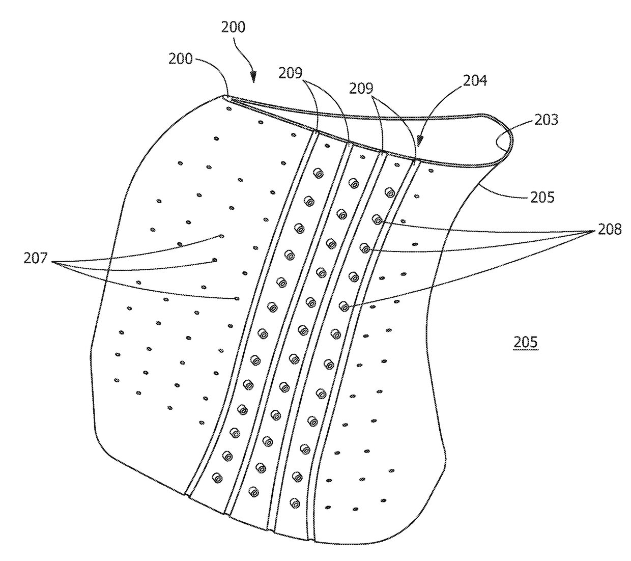
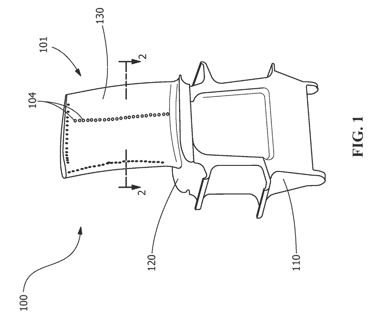
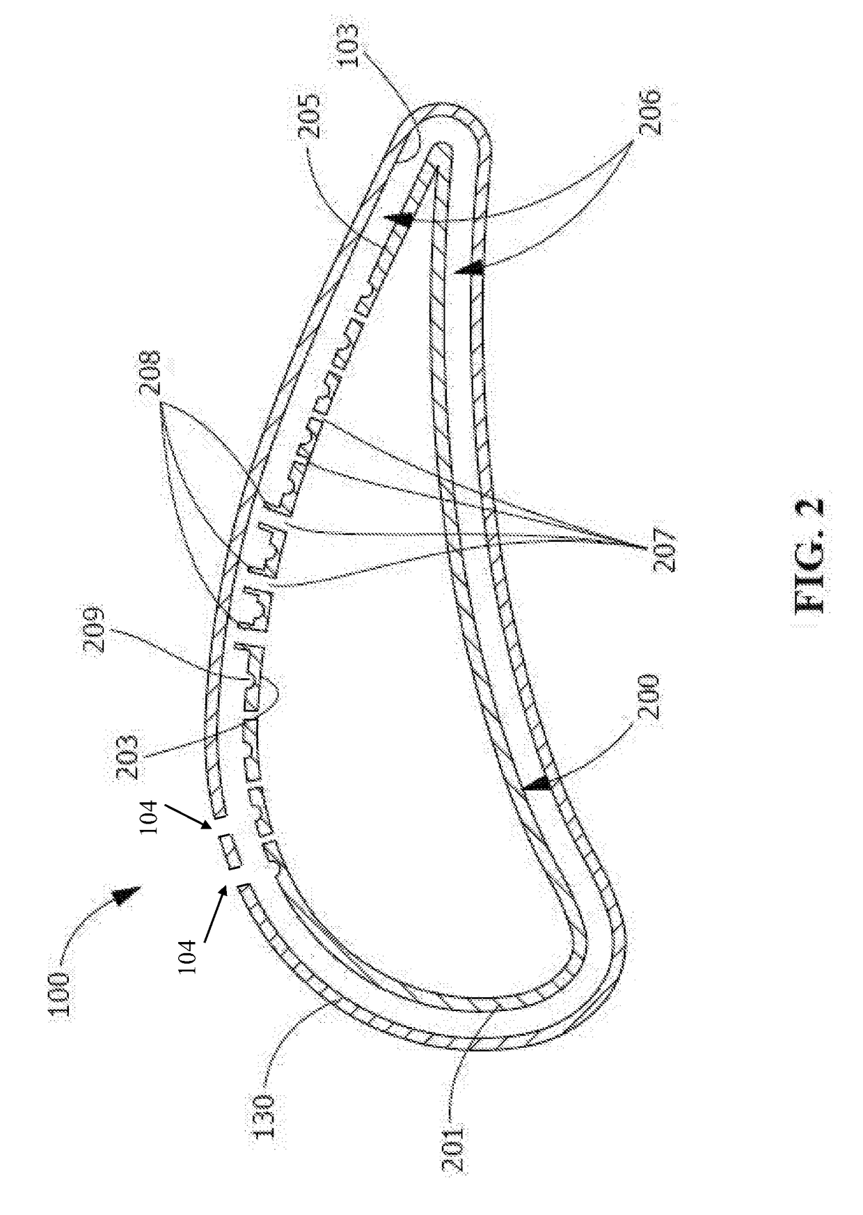
[0030]FIGS. 1-3 illustrate one embodiment of an article 100 (FIGS. 1-2) and a device 200 (FIGS. 2-3) positioned within the article 100. The article 100 and / or the device 200 are formed according to any suitable manufacturing method. Suitable manufacturing methods include, but are not limited to, casting, machining, additive manufacturing, or a...


PUM


Abstract

Various embodiments include a heat transfer device, while other embodiments include a turbine component. In some cases, the device can include: a body portion having an inner surface and an outer surface, the inner surface defining an inner region; at least one aperture in the body portion, the at least one aperture positioned to direct fluid from the inner region through the body portion; and at least one fluid receiving feature formed in the outer surface of the body portion, the at least one fluid receiving feature positioned to receive post-impingement fluid from the at least one aperture, wherein the at least one aperture does not define any portion of the at least one fluid receiving feature, and the at least one fluid receiving feature segregates relatively higher velocity post-impingement fluid from relatively lower velocity fluid within an impingement cross-flow region.

Description

FIELD OF THE INVENTION[0001]The present disclosure relates to heat transfer. More particularly, the present invention is directed to a heat transfer device and approaches for transferring heat from an article such as a turbine airfoil.BACKGROUND OF THE INVENTION[0002]Turbine systems are continuously being modified to increase efficiency and decrease cost. One method for increasing the efficiency of a turbine system includes increasing the operating temperature of the turbine system. However, operating at high temperatures for extended periods often requires using newer materials capable of withstanding those conditions.[0003]In addition to modifying component materials and coatings, one common method of increasing temperature capability of a turbine component includes the use of impingement cooling. Impingement cooling generally includes directing a cooling fluid through one or more apertures within an inner region of an article, the cooling fluid contacting (i.e., impinging upon) a...

Claims


Application Information

Patent Timeline
IPC IPC(8): F01D5/18
CPCF01D5/186F05D2220/32F05D2260/221F05D2260/201F05D2220/31F05D2240/30F05D2250/232F01D25/14F05D2250/231F01D5/189F05D2260/205F01D25/12F05D2260/204F05D2250/294
Inventor HOSKIN, ROBERT FRANKTALLMAN, JAMES ALBERT
Owner GENERAL ELECTRIC CO
Why Eureka
Try Eureka