Gas impingement device, recording substrate treatment apparatus and printing system comprising such gas impingement device

Active Publication Date: 2017-09-14
OCE TECH
View PDF1 Cites 0 Cited by
  • Summary
  • Abstract
  • Description
  • Claims
  • Application Information

AI Technical Summary

Benefits of technology

The present invention provides a gas impingement device that can be used in a high speed cut-sheet printing system. The device can operate at a high gas impingement velocity without causing the sheets to be blown away or to become curved during transportation. The device comprises a skewed pattern of gas outlets that reduces the risk of impinging a front or trailing edge of a sheet with gas. S smaller diameter gas outlets are used at both the entry and exit sides of the device to minimize the impact of gas impingement on the front and trailing edges of the sheets. These technical effects allow for improved printing performance and quality.

Problems solved by technology

Although design rules for optimum air impingement arrangements are known and can be found in literature, one often sees inferior impingement techniques (like using slits instead of a hole pattern, or with non-optimum hole geometries or with non-optimum substrate distance, or with far too low air velocity).
At such high printing speeds, the drying capacity of a drying and fixing device becomes limited due to formation of a saturated boundary layer of a (volatile) solvent, e.g. water, at and near the surface of the recording substrate, limiting further evaporation of said solvent.
It is a disadvantage of the known impingement devices that such devices are not suitable for use in high speed cut-sheet printing systems.
For example, if such impingement devices are used for high velocity gas impingement in a cut-sheet printing system, sheets of recording substrate are easily blown away, and / or floating and / or curling of the transported sheet of recording substrate may occur, in particular in printing systems wherein sheets of a recording substrate are temporarily fixated onto a transportation device by, e.g. vacuum fixation, electrostatic fixation or wherein sheets of a recording substrate are transported through nips.
These are undesired effects because the reliability of the printing process and / or sheet transport may be adversely affected.

Method used


Image

  • Gas impingement device, recording substrate treatment apparatus and printing system comprising such gas impingement device
  • Gas impingement device, recording substrate treatment apparatus and printing system comprising such gas impingement device
  • Gas impingement device, recording substrate treatment apparatus and printing system comprising such gas impingement device

Examples


Embodiment Construction

[0063]The present invention will now be described with reference to the accompanying drawings, wherein the same or similar elements are identified with the same reference numeral.

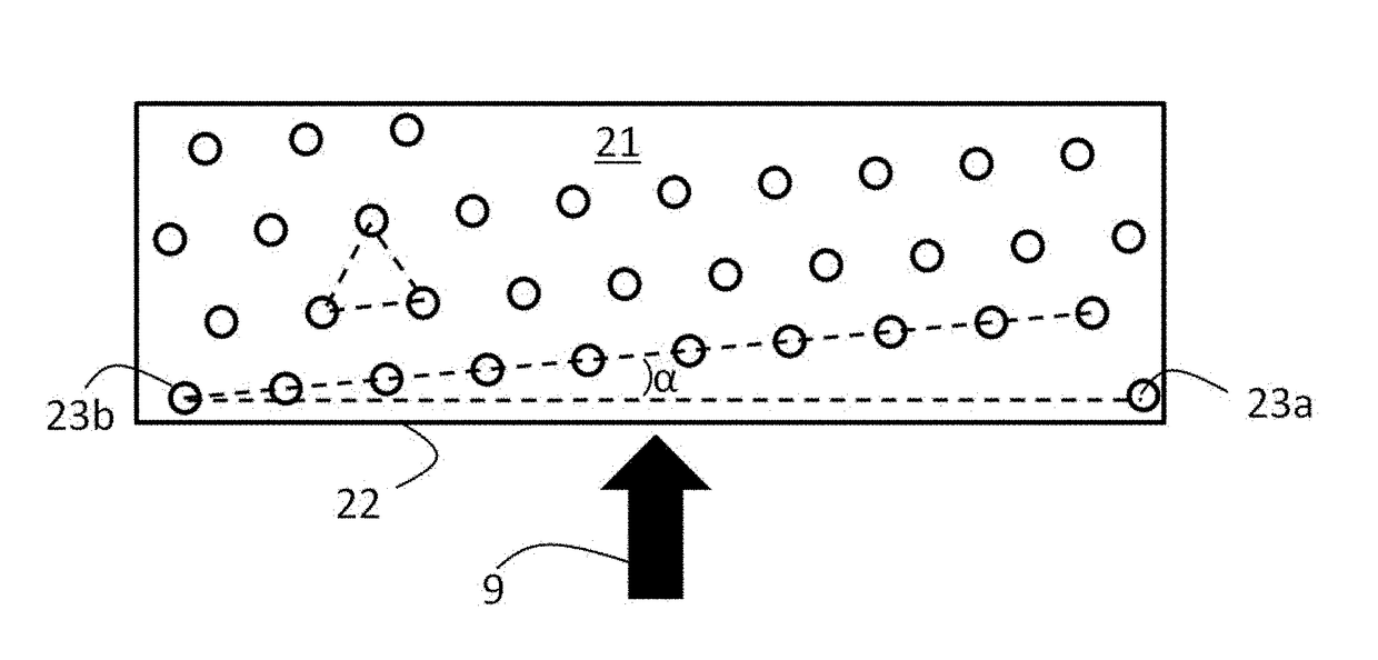
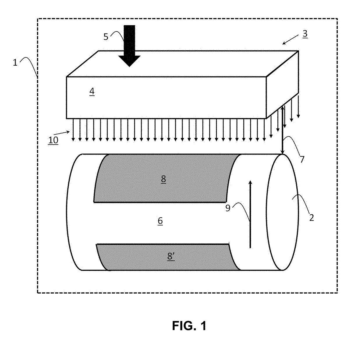
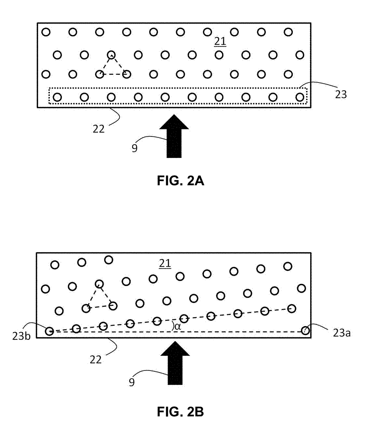
[0064]FIG. 1 is a schematic representation of a substrate treatment apparatus 1 comprising a transporting device 2, in this particular example being a drum, and a gas impingement device 3 comprising a hollow body 4, a gas inlet, indicated with arrow 5 and a plurality of gas outlets arranged in a pattern in a first surface of the hollow body 4 (not shown here). The first surface is arranged opposite a transporting surface 6 of the transporting device and at a distance 7 from the transporting surface 6, in this particular example substantially 8*doutlet. In operation, the transporting device 2 carries one or more printed sheets of recording substrate 8, and 8′ on transporting surface 6, which sheets are transported in a direction as indicated with arrow 9. In operation, a gas flow, usually air, is fed to the ...


PUM


Abstract

A gas impingement device includes a first surface including a pattern of a plurality of gas outlets, the pattern including a number of substantially parallel rows of gas outlets, the rows arranged in a direction, which direction is at a skew angle α with a front edge of the first surface of the gas impingement device. A recording substrate treatment apparatus and a printing system including such a gas impingement device and a method of drying a recording substrate by using the gas impingement device are also disclosed.

Description

CROSS-REFERENCE TO RELATED APPLICATIONS[0001]This application is a Continuation of PCT International application No. PCT / EP2015 / 077195, filed on Nov. 20, 2015. PCT / EP2015 / 077195 claims priority under 35 U.S.C. §119 to Application No. 14195318.2, filed in Europe on Nov. 28, 2014. The entirety of each of the above-identified applications is expressly incorporated herein by reference.BACKGROUND OF THE INVENTION[0002]1. Field of the Invention[0003]The present invention relates to a gas impingement device. The gas impingement device according to the present invention can be suitably used in a drying and / or fixation device, in particular in a drying and / or fixation device used in an (inkjet) printing device.[0004]2. Background of the Invention[0005]In general, air impingement can be used in drying techniques for enhancing evaporation of water. Air impingement is well known in the paper drying technology. In a typical dryer, preferably, first heat is submitted to the paper in order to incr...

Claims


Application Information

Patent Timeline
IPC IPC(8): G03G15/20B41J11/00G03G15/32B41F23/04
CPCG03G15/2021B41F23/0469B41F23/0466B41J11/002G03G15/321G03G15/2017B41F23/044B41J11/0015G03G15/323B41J11/00216B41J11/0022
Inventor RAMACKERS, HENDRIKUS G.M.KERSTEN, STAN H.P.
Owner OCE TECH
Why Eureka
Try Eureka