
Acoustic wave filter

Pending Publication Date: 2021-05-13
MURATA MFG CO LTD
View PDF0 Cites 0 Cited by
  • Summary
  • Abstract
  • Description
  • Claims
  • Application Information

AI Technical Summary

Benefits of technology

The patent describes an acoustic wave filter device that uses a piezoelectric film and a piezoelectric single crystal substrate with specific lamination structures, material properties, cut-angles, and thicknesses to achieve desired bandpass characteristics. The device can also include an energy confinement layer to improve its performance. The patent also describes the use of an IDT electrode with a specific shape and parameters. The operation principle of the acoustic wave filter is based on the piezoelectric effect, which allows for the generation and propagation of acoustic waves. The technical effects of the patent include improved bandpass characteristics, reduced energy loss, and improved performance of the acoustic wave filter device.

Problems solved by technology

However, for example, in a case where a bridging capacitance element is connected to a parallel arm resonator or a parallel arm resonator includes a withdrawal weighting electrode, return loss in the vicinity of the anti-resonant frequency of the parallel arm resonator deteriorates.
In a ladder acoustic wave filter, since the anti-resonant frequency of the parallel arm resonator is normally disposed in the pass band, there is a problem that when the return loss at the anti-resonant frequency deteriorates, the insertion loss of the pass band of the acoustic wave filter deteriorates.

Method used


Image

  • Acoustic wave filter
  • Acoustic wave filter
  • Acoustic wave filter

Examples


embodiment 1

Preferred Embodiment 1

1.1 Circuit Configuration of Acoustic Wave Filter

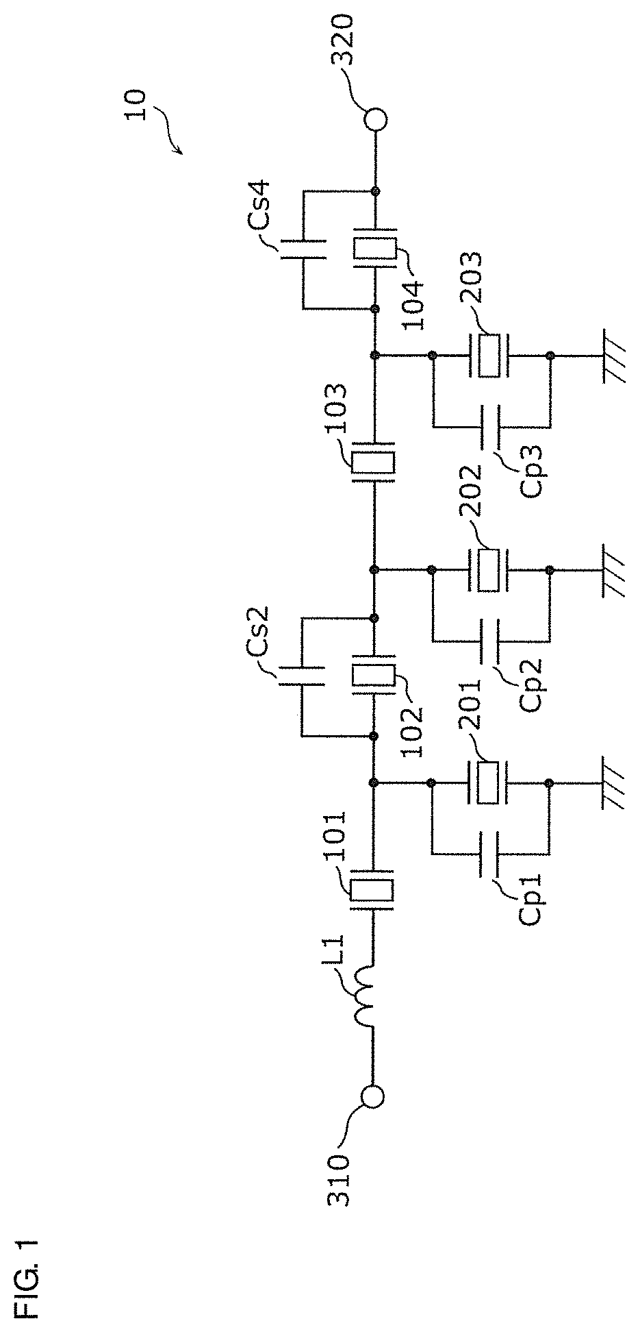
[0027]FIG. 1 is a circuit configuration diagram of an acoustic wave filter 10 according to Preferred Embodiment 1 of the present invention. As illustrated in FIG. 1, the acoustic wave filter 10 includes serial arm resonators 101, 102, 103, and 104, parallel arm resonators 201, 202, and 203, bridging capacitances Cs2 and Cs4, an inductor L1, and input / output terminals 310 and 320.

[0028]The serial arm resonators 101 to 104 are disposed on a path connecting the input / output terminal 310 (first input / output terminal) and the input / output terminal 320 (second input / output terminal), and are connected in series to each other. Furthermore, the parallel arm resonators 201 to 203 are each disposed between a node on the path and a ground terminal. With the above-described connection configuration of the serial arm resonators 101 to 104 and the parallel arm resonators 201 to 203, the acoustic wave filter 10 defines a ladder...

embodiment 2

Preferred Embodiment 2

[0097]In Preferred Embodiment 1, although the configuration in which the bridging capacitance is added to the parallel arm resonator has been described as the configuration to reduce the resonance fractional band width of the parallel arm resonance circuit, in Preferred Embodiment 2 of the present invention, a configuration in which the IDT electrode of the parallel arm resonator includes a withdrawal electrode will be described as a configuration to reduce the resonance fractional band width of the parallel arm resonance circuit.

2.1 Circuit Configuration of Acoustic Wave Filter

[0098]FIG. 8 is a circuit configuration diagram of an acoustic wave filter 20 according to Preferred Embodiment 2. As illustrated in the diagram, the acoustic wave filter 20 includes serial arm resonators 101, 102, 103, and 104, parallel arm resonators 251, 252, and 253, bridging capacitances Cs2 and Cs4, inductor L1, and input / output terminals 310 and 320.

[0099]The acoustic wave filter ...


PUM


Abstract

An acoustic wave filter includes at least one serial arm resonance circuit on a path connecting input / output terminals, and at least one parallel arm resonance circuit between a node on the path and a ground, in which each of the at least one serial arm resonance circuit and the at least one parallel arm resonance circuit includes an acoustic wave resonator, a first parallel arm resonance circuit of the at least one parallel arm resonance circuit includes a bridging capacitor connected in parallel to the acoustic wave resonator, an anti-resonant frequency of the first parallel arm resonance circuit is positioned on a higher-frequency side than the pass band, and a resonant frequency of a first serial arm resonance circuit of the at least one serial arm resonance circuit is positioned on a lower-frequency side than the anti-resonant frequency of the first parallel arm resonance circuit.

Description

CROSS REFERENCE TO RELATED APPLICATIONS[0001]This application claims the benefit of priority to Japanese Patent Application No. 2018-152203 filed on Aug. 13, 2018 and is a Continuation Application of PCT Application No. PCT / JP2019 / 031014 filed on Aug. 6, 2019. The entire contents of each application are hereby incorporated herein by reference.BACKGROUND OF THE INVENTION1. Field of the Invention[0002]The present invention relates to an acoustic wave filter.2. Description of the Related Art[0003]An acoustic wave filter has been put into practical use as a band filter used in an RF (Radio Frequency) circuit of a communication apparatus or the like. From a viewpoint of effectively utilizing frequency resources for wireless communication, a large number of frequency bands are allocated as communication bands for mobile phones and the like, and therefore the interval between adjacent frequency bands becomes narrow. In view of this allocation of the frequency band, in the acoustic wave fil...

Claims


Application Information

Patent Timeline
IPC IPC(8): H03H9/64H03H9/25H03H9/02
CPCH03H9/6483H03H9/6406H03H9/02992H03H9/02228H03H9/25H03H9/14526H03H9/0274H03H9/1457H03H9/02574H03H9/14541H03H9/725
Inventor TAKATA, TOSHIAKI
Owner MURATA MFG CO LTD
Learn More