
Wreath Decoration System

a wreath and decoration technology, applied in the field of wreath decoration systems, can solve the problems of not providing means for secure light decorations, and fasteners often failing to properly position light ornaments on the desired object, so as to facilitate the mounting of illumination sources and enhance the ornamental design of wreaths

Active Publication Date: 2021-07-15
MCNAMARA RICHARD J +1
View PDF0 Cites 4 Cited by
  • Summary
  • Abstract
  • Description
  • Claims
  • Application Information

AI Technical Summary

Benefits of technology

The present invention is a wreath decoration system that allows users to mount a custom-made acrylic plate to enhance the ornamental design of the wreath. The system includes a support beam that elevates the illumination source just below the branches in the center of the wreath, making it invisible from the front. Users can selectively control the voltage source, light intensity, color change, and display routines, and can also control the illumination source and light decorations remotely through an external computing device. The technical effects of this invention include improved ornamental design and versatility in controlling the illumination source and light decorations.

Problems solved by technology

However, light decorations do not usually provide means to secure light decorations to the other decorations, making users to come up with ways to fasten the whole assembly together.
Unfortunately, these fasteners often fail to properly position the light ornaments on the desired object, such as centering a light decoration on a wreath.

Method used


Image

  • Wreath Decoration System
  • Wreath Decoration System
  • Wreath Decoration System

Examples


Embodiment Construction

[0016]All illustrations of the drawings are for the purpose of describing selected versions of the present invention and are not intended to limit the scope of the present invention.

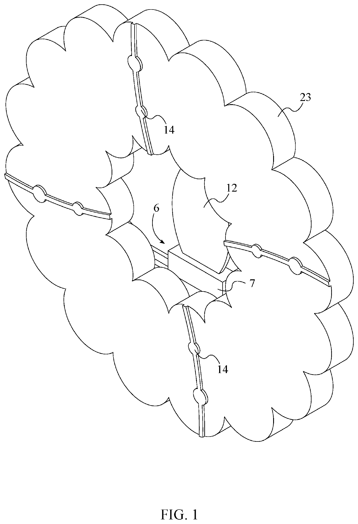
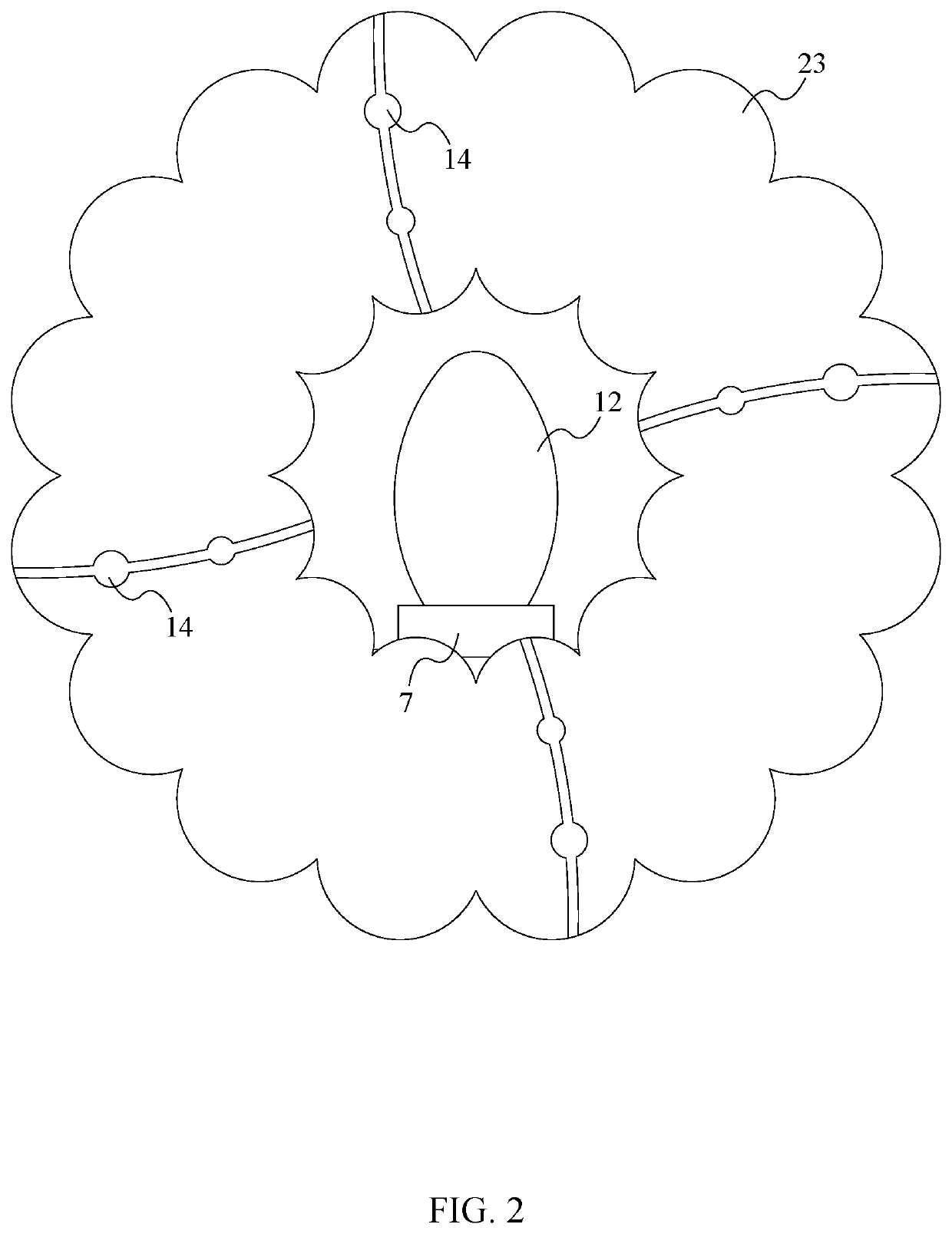
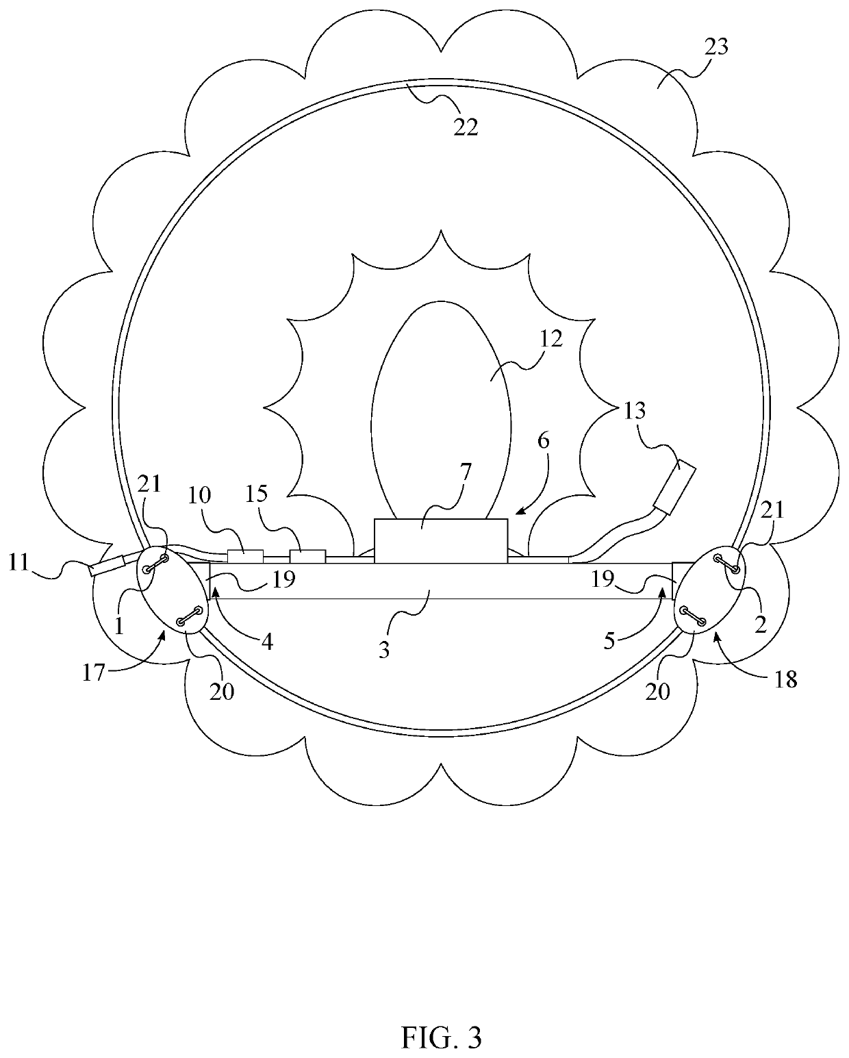
[0017]The present invention is a wreath decoration system that enables users to mount a decorative acrylic plate to a wreath decoration to enhance the decoration. As can be seen in FIG. 1 through 3, the present invention may comprise a first wire fastener 1, a second wire fastener 2, a support beam 3, a primary illumination source 6, a microcontroller 10, and a power supply system 11. The first wire fastener 1 and the second wire fastener 2 help secure the support beam 3 to the wire frame 22 of the wreath 23. The first wire fastener 1 and the second wire fastener 2 also help offset the support beam 3 from the wire frame 22 to hide the support beam 3 behind the wreath 23. The support beam 3 helps center the primary illumination source 6 on the bottom of the wreath 23. The primary illumination source 6 ill...


PUM


Abstract

A wreath decoration system is used to enable users to mount a decorative acrylic plate to a wreath to enhance the decoration of the wreath. The system includes a first wire fastener, a second wire fastener, a support beam, a primary illumination source, a microcontroller, and a power supply system. The first wire fastener and the second wire fastener help secure the support beam to the wreath. The first wire fastener and the second wire fastener also help position the support beam behind the wreath so that the support beam is hidden behind the wreath leaves. The support beam centers the primary illumination source on the wreath. The primary illumination source illuminates any decoration positioned on the center of the wreath. The microcontroller enables the configuration of the settings of the primary illumination source. The power supply system supplies the voltage necessary to the primary illumination source and the microcontroller.

Description

[0001]The current application claims a priority to the U.S. Provisional Patent application Ser. No. 62 / 960,570 filed on Jan. 13, 2020.[0002]The current application is also a continuation-in-part (CIP) application of the U.S. design application Ser. No. 29 / 721,708 filed on Jan. 22, 2020.FIELD OF THE INVENTION[0003]The present invention generally relates to decoration mounts and wreath accessories. More specifically, the present invention provides an illumination system for etched acrylic plate decorations for wreaths.BACKGROUND OF THE INVENTION[0004]Light decorations are an essential part of home decorations for the holidays. Light decorations come in various types, shapes, and sizes. For example, some of the most common holiday light decorations are Christmas lights that are often attached to Christmas trees, walls, handrails, etc. Often these lights decorations are combined with other holiday decorations to enhance the overall design, such as covering nativity scenes with lights or...

Claims


Application Information

Patent Timeline
Patent Type & Authority Applications(United States)
IPC IPC(8): F21V21/16F21V23/00F21V23/06F21S4/10F21V23/04
CPCF21V21/16F21V23/003F21V23/0435F21S4/10F21V23/06F21V33/0028F21Y2115/10A01G5/04
Inventor MCNAMARA, RICHARD J.M. SMITH, JUDITH M.
Owner MCNAMARA RICHARD J
Learn More