Fingerprint sensing system and method for providing user input on an electronic device using a fingerprint sensor

a fingerprint sensor and fingerprint technology, applied in the direction of instruments, dashboard fitting arrangements, transportation and packaging, etc., can solve the problems of creating more complex user inputs, inefficient finger movements, and ineffective finger movements

Active Publication Date: 2021-07-29
FINGERPRINT CARDS ANACATUM IP AB
View PDF0 Cites 0 Cited by
  • Summary
  • Abstract
  • Description
  • Claims
  • Application Information

AI Technical Summary

Benefits of technology

[0010]The present invention is based upon the realization that by measuring force value differences on sub-groups of fingerprint sensing elements it is possible to create user input without the need for the user to lift the finger and provide input with a second touch. In this way, it is possible to emulate a so-called “pointing-stick” functionality or generally a “gesture control” functionality using a fingerprint sensor.
[0024]The relative location of the pair of sensing elements may provide directionality for the user input, and the amount of force value difference may provide a speed indication for the user input. Hereby a user-friendly user input control is provided.
[0031]The protective top dielectric structure, which also may be referred to as a coating, may advantageously be at least 20 μm thick and have a high dielectric strength to protect the underlying structures of the fingerprint sensing device from wear and tear as well as from electrostatic discharge (ESD). Even more advantageously, the protective top layer may be approximately 100 μm thick, or in the range of 500-700 μm thick, or even thicker.

Problems solved by technology

These gestures are as such quite inefficient from a finger movement perspective.
Thus, more complex user inputs may be created by combining force value differences from more than one sub-group pair of sensing elements.

Method used


Image

  • Fingerprint sensing system and method for providing user input on an electronic device using a fingerprint sensor
  • Fingerprint sensing system and method for providing user input on an electronic device using a fingerprint sensor
  • Fingerprint sensing system and method for providing user input on an electronic device using a fingerprint sensor

Examples


Embodiment Construction

[0049]In the present detailed description, various embodiments of the method and electronic device according to the present invention are mainly described with reference to a substantially square fingerprint sensor arranged adjacent to the touch display of a mobile phone.

[0050]It should be noted that this by no means limits the scope of the present invention, which equally well includes, for example, other electronic devices such as tablets, computers or watches. Furthermore, the fingerprint sensor may have any other shape. For instance, the fingerprint sensor may be provided as an elongated rectangle.

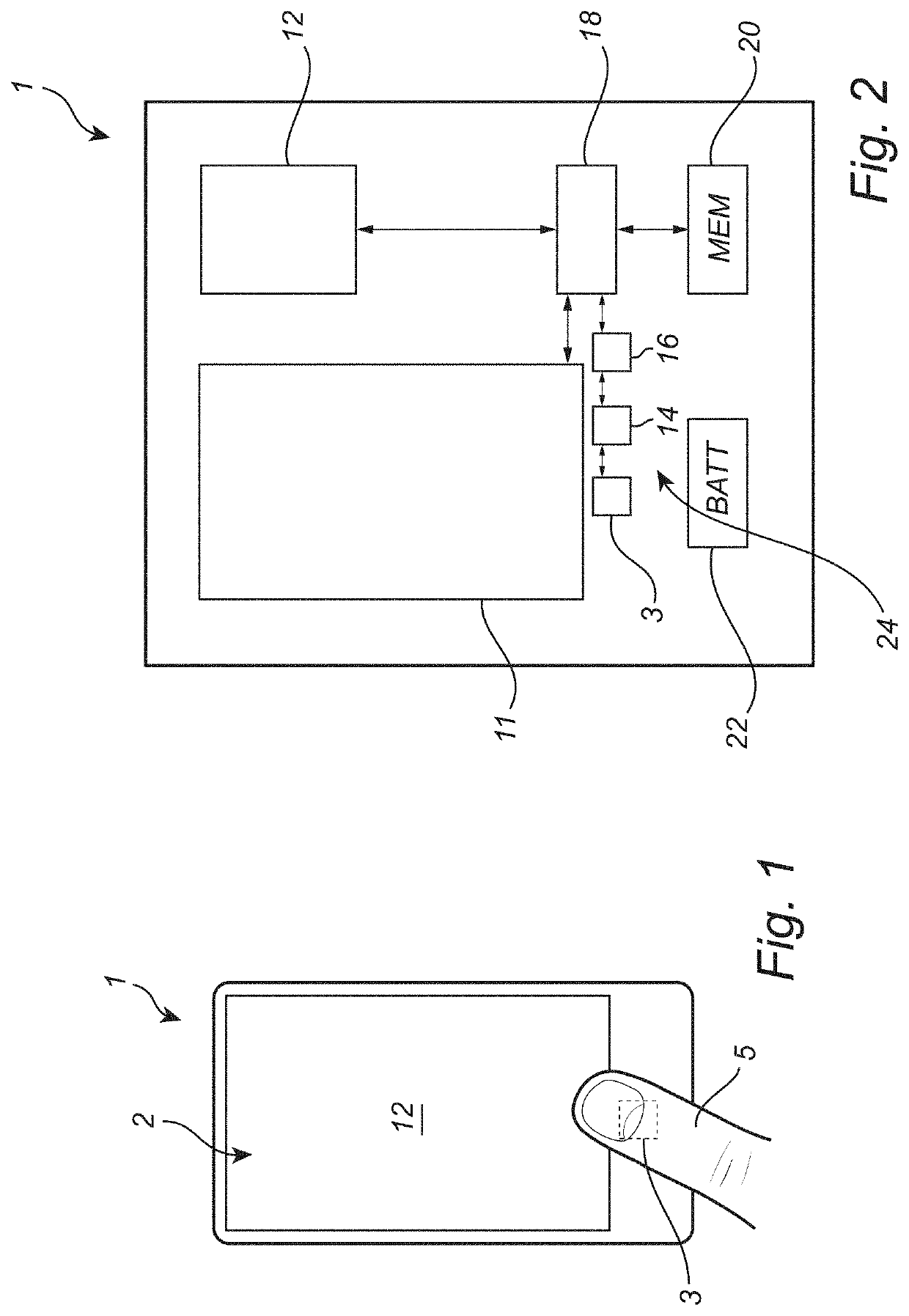
[0051]Referring to FIG. 1, an electronic device, here in the form of mobile phone 1, comprises a touch display 2 and a fingerprint sensor 3. The touch display 2 comprises a touch sensor for touch-based control of the mobile phone 1 and a display acting as a user interface.

[0052]In FIG. 1, a finger 5 of the user of the mobile phone 1 makes a finger touch on the surface of the fingerprin...


PUM


Abstract

A method for providing user input on an electronic device comprising a fingerprint sensor comprising an array of sensing elements. Acquiring partial fingerprint images of a finger touching a finger touch surface of the fingerprint sensor from at least two sub-groups of sensing element. Determining a respective force value indicative of a force applied on the finger touch surface at each of the sub-groups of sensing elements when the partial fingerprints were acquired, based on the partial fingerprint images acquired from the respective sub-group of sensing elements. Determining a force value difference between a pair of the determined force values. Determining a user input based on the determined force value difference, and based on the relative location between the sub-groups of sensing elements in the pair associated with the force value difference.

Description

FIELD OF THE INVENTION[0001]The present invention relates to a method for providing user input on an electronic device using a fingerprint sensor. The invention also relates to a fingerprint sensing system, to an electronic device, and to a vehicle comprising a fingerprint sensing system.BACKGROUND OF THE INVENTION[0002]Various types of biometric systems are used more and more in order to provide for increased security and / or enhanced user convenience.[0003]In particular, fingerprint sensing systems have been adopted in, for example, consumer electronic devices, thanks to their small form factor, high performance and user acceptance.[0004]In some applications, it would be desirable to be able to use finger touches on a fingerprint sensor for navigation control for an electronic device. With fingerprint sensor navigation, the user may be able to create navigation events by swiping the finger over the sensor.[0005]One example of using a fingerprint sensor for navigation is described i...

Claims


Application Information

Patent Timeline
Patent Type & Authority Applications(United States)
IPC IPC(8): G06F3/0354G06K9/00G06V40/12G06V40/13
CPCG06F3/03547G06K9/0002B60K37/06G06F2203/0338G06K9/00087G06F3/0485G06V40/13G06F3/041G06F3/033G06V40/1347B60K2370/782B60K2370/143G06V40/1306G06V40/1365G06F1/1626G06V40/1359
Inventor BJERRE, TROELSANDERSEN, KLAUS S.
Owner FINGERPRINT CARDS ANACATUM IP AB
Why Eureka
Try Eureka