Boat propulsion system

a propulsion system and boat technology, applied in the direction of marine propulsion, propulsion transmission, vessel construction, etc., can solve the problems of disadvantageous increase of maximum speed, difficult to achieve both acceleration performance and maximum speed desired by users, and difficult to improve acceleration performance at a low speed

a propulsion system and boat technology, applied in the direction of marine propulsion, propulsion transmission, vessel construction, etc., can solve the problems of disadvantageous increase of maximum speed, difficult to achieve both acceleration performance and maximum speed desired by users, and difficult to improve acceleration performance at a low speed

US20090227160A1Active Publication Date: 2009-09-10YAMAHA MOTOR CO LTD

Image

  • Boat propulsion system
  • Boat propulsion system
  • Boat propulsion system

Examples


Embodiment Construction

[0025]Hereinafter, description will be made of preferred embodiments of the present invention with reference to the drawings.

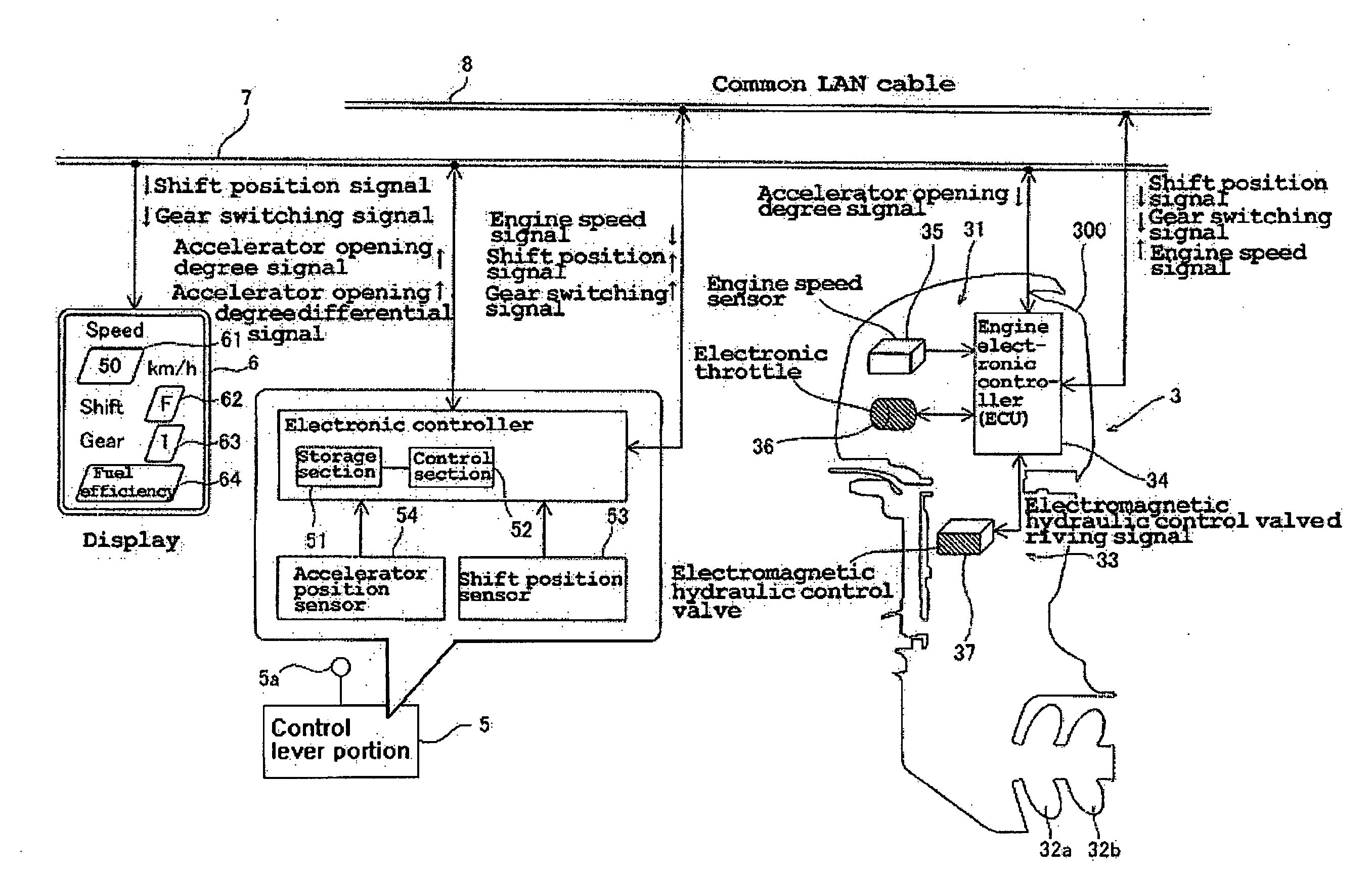
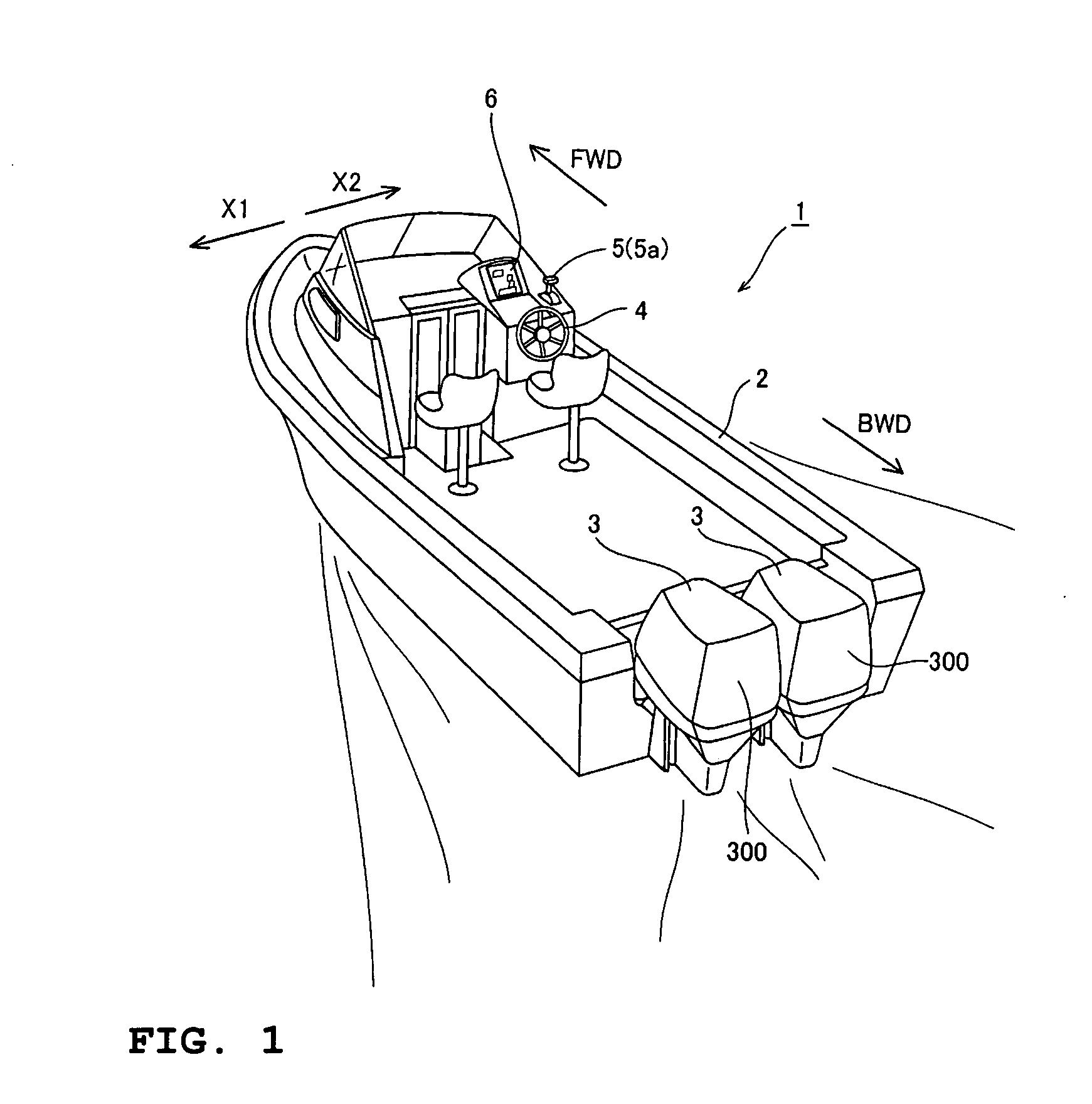
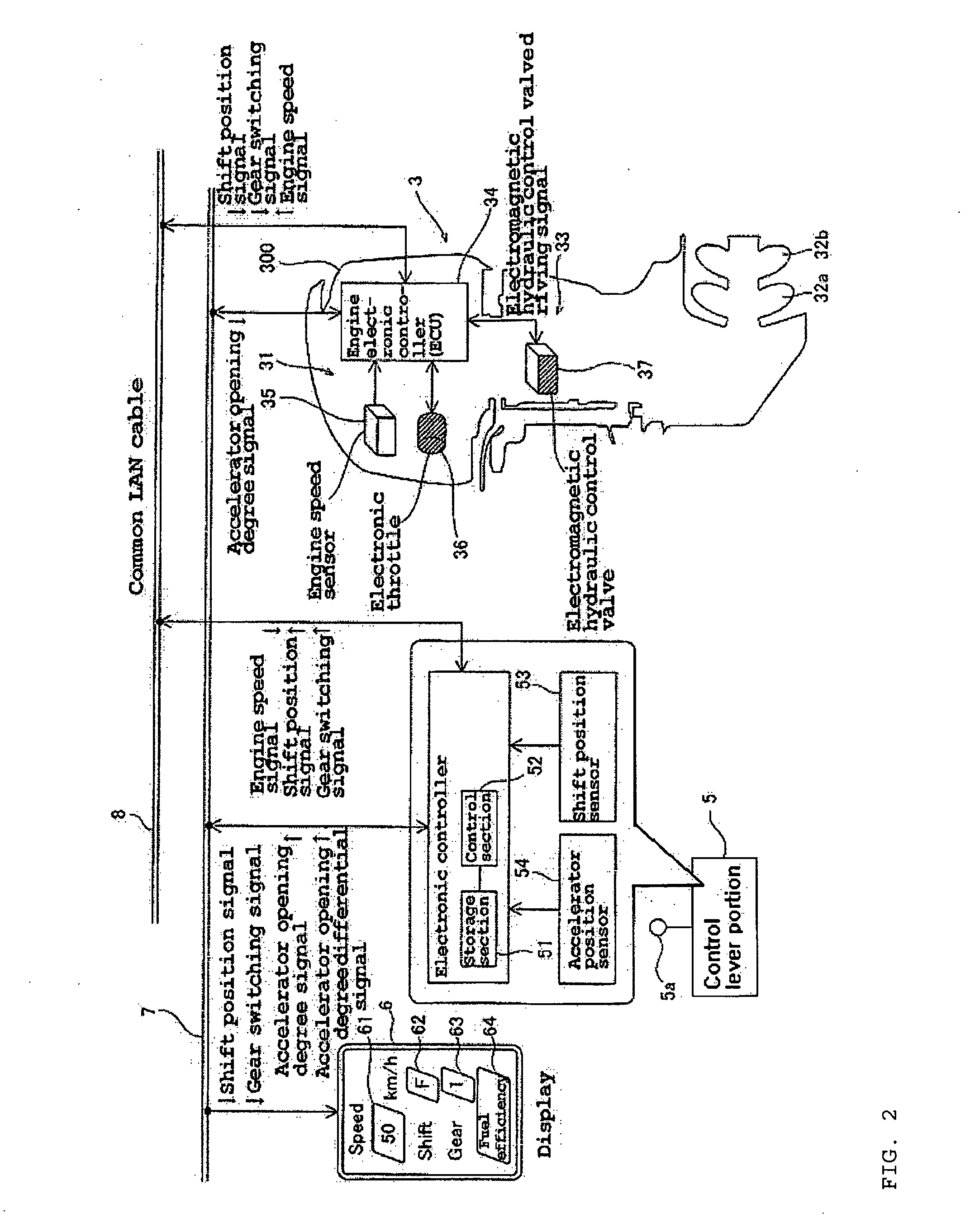
[0026]FIG. 1 is a perspective view showing a boat equipped with a boat propulsion system in accordance with a preferred embodiment of the present invention. FIG. 2 is a block diagram showing the configuration of the boat propulsion system in accordance with a preferred embodiment of the present invention. FIGS. 3 to 7 each illustrate the detailed configuration of the boat propulsion system in accordance with a preferred embodiment shown in FIG. 1. In the drawings, FWD denotes the forward direction of the boat while BWD denotes the backward direction of the boat. First, a description will be made of the configuration of the boat 1 and the boat propulsion system provided in the boat 1 in accordance with a preferred embodiment with reference to FIGS. 1 to 7.

[0027]As shown in FIG. 1, the boat 1 in accordance with a preferred embodiment is provided with a hull 2 th...


PUM


Abstract

A boat propulsion system includes a gear shift mechanism arranged to transmit a driving force generated by an engine to first and second propellers at one of at least a low speed reduction ratio and a high speed reduction ratio, and a control section arranged to perform control so as to shift a speed reduction ratio of the gear shift mechanism based on first and second gear shift control maps when an acceleration command from a user is detected. The first and second gear shift control maps define a region to shift the speed reduction ratio of the gear shift mechanism using two parameters, preferably a rotational speed of the engine and a lever opening degree of a lever of a control lever portion. The boat propulsion system achieves both the acceleration performance and the maximum speed desired by a user.

Description

BACKGROUND OF THE INVENTION[0001]1. Field of the Invention[0002]The present inventions relates to a boat propulsion system, and more specifically to a boat propulsion system including an engine.[0003]2. Description of the Related Art[0004]A boat propulsion unit including an engine is conventionally known (see JP-A-Hei 9-263294, for example). JP-A-Hei discloses a boat propulsion unit including an engine and a power transmission mechanism for transmitting a driving force of the engine to a propeller at a certain fixed speed reduction ratio. In the boat propulsion unit, the driving force of the engine is directly transmitted to the propeller via the power transmission mechanism so that the propeller speed increases in proportion to the engine speed as the engine speed increases.[0005]However, the boat propulsion unit (boat propulsion system) disclosed in JP-A-Hei 9-263294 has a disadvantage in that it is difficult to improve the acceleration performance at a low speed in the case where...

Claims


Application Information

Patent Timeline
10 Sep 2009
Publication
US20090227160A1
IPC
B63H21/21
CPC
B63H21/213
Inventors
SUZUKI, TAKAYOSHI; NAKAMURA, DAISUKE