
A power tool

Pending Publication Date: 2021-08-05
TECHTRONIC CORDLESS GP
View PDF0 Cites 0 Cited by
  • Summary
  • Abstract
  • Description
  • Claims
  • Application Information

AI Technical Summary

Benefits of technology

The third aspect of the invention causes a front-to-rear power tool to have a higher center of gravity, which results in a downward force on the work tip.

Problems solved by technology

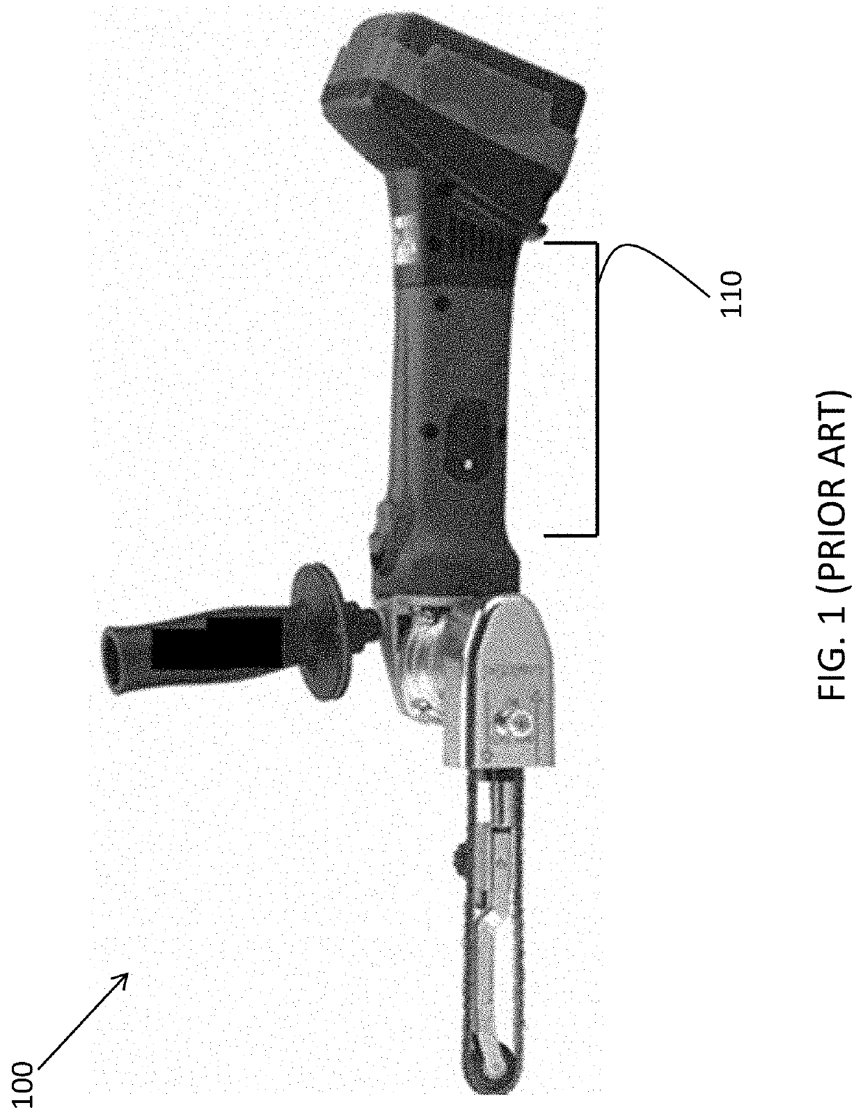
However, the gripping region is often large and difficult to grip as it may enclose components of the power tool, leading to low user comfort and control.

Method used


Image

  • A power tool
  • A power tool
  • A power tool

Examples


Embodiment Construction

[0033]The following description is given by way of example only to illustrate preferred embodiments of the invention. In particular, the language and terminology used herein is for descriptive purposes only and is not intended to limit the scope or functionality of the invention. The invention may be employed in various combinations or embodiments utilizing various elements and means not explicitly described herein, but within the knowledge and skill of one skilled in the art.

[0034]In the claims which follow and in the preceding description of the invention, except where the context requires otherwise due to express language or necessary implication, the word “comprise” or variations such as “comprises” or “comprising” is used in an inclusive sense, i.e. to specify the presence of the stated features but not to preclude the presence or addition of further features in various embodiments of the invention.

[0035]Terms such as “horizontal”, “vertical”, “upwards”, “downwards”, “above”, “...


PUM


Abstract

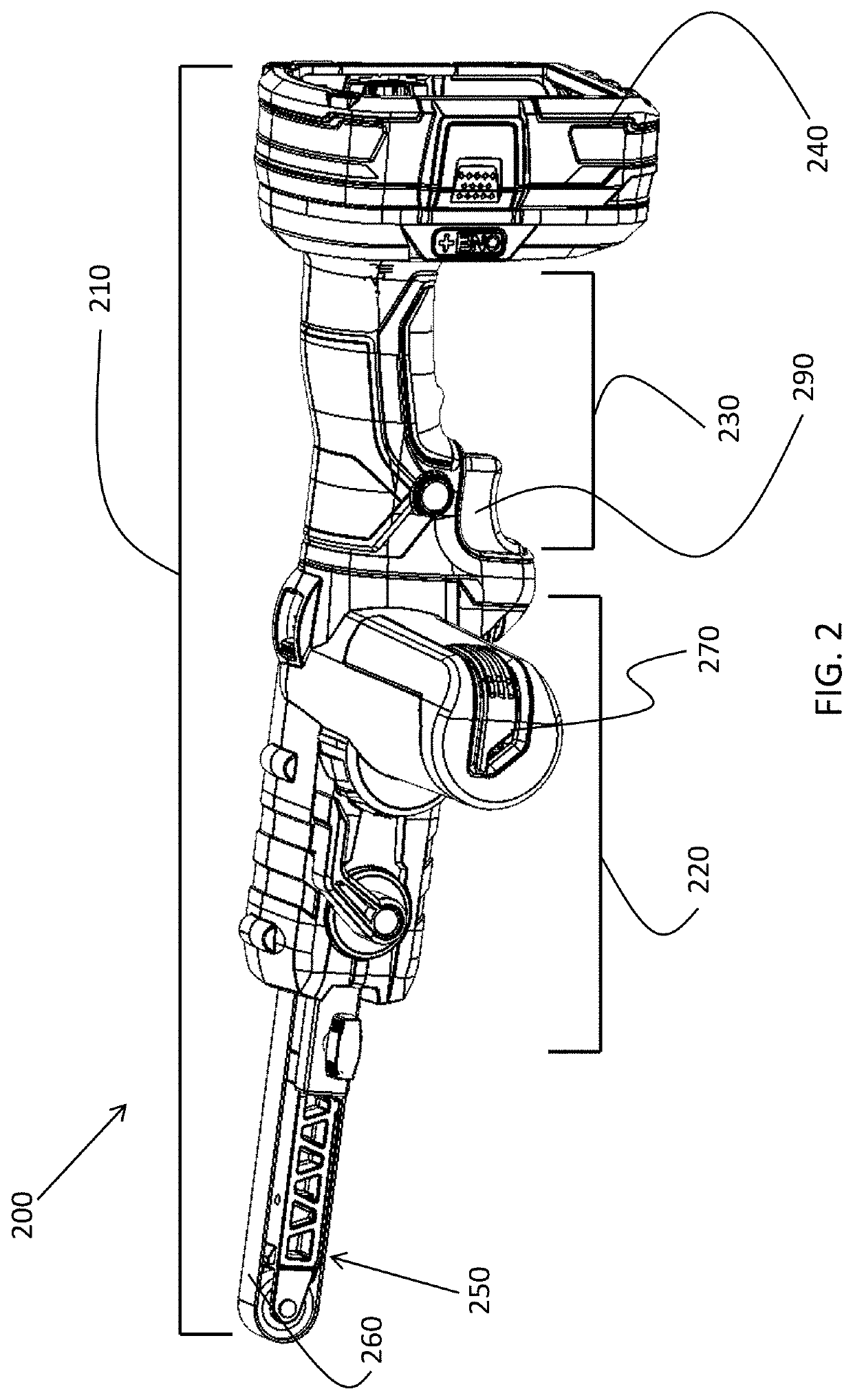
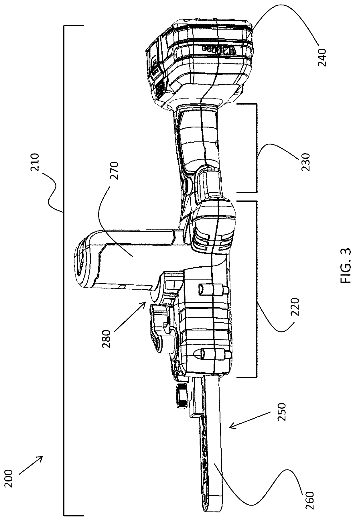
A power tool includes a generally elongate tool housing defining a longitudinal axis parallel with the length of the tool housing, a work tip located at a first end of the tool housing for supporting a work member, and a power source interface located at a second end of the tool housing for supporting a removable power source. The tool housing includes an elongate handle-shaped grip region between the work tip and power source interface, and generally parallel to the longitudinal axis, and a drive region that substantially encloses a motor separately from the handle-shaped grip region. The motor is located between the handle-shaped grip region and the work tip.

Description

FIELD OF INVENTION[0001]The present invention relates to power tools and a housing for use in power tools. Particularly, but not exclusively, the present invention relates to a power file.BACKGROUND OF INVENTION[0002]Tasks typically performed by a power tool, such as filing or sanding, generally require steady control of the power tool by a user. This user control is provided by a gripping region in the housing which is gripped by the user. However, the gripping region is often large and difficult to grip as it may enclose components of the power tool, leading to low user comfort and control. Power tools that provide improved user handling and comfort are desired.SUMMARY OF INVENTION[0003]In light of the foregoing background, it is an object of the present invention to provide a power tool which addresses the above technical problems.[0004]In a first aspect of the present invention, there is provided a power tool comprising a generally elongate tool housing defining a longitudinal a...

Claims


Application Information

Patent Timeline
IPC IPC(8): B24B23/06H02K7/14H02K7/00
CPCB24B23/06H02K7/003H02K7/145B25F5/02
Inventor MOK, KWOK TINGYE, ZHI QIANG
Owner TECHTRONIC CORDLESS GP
Learn More