Door locking system

a technology for locking systems and doors, applied in the field of door locking systems, can solve the problems of requiring additional installation space, and achieve the effects of reducing the risk of children locking themselves, preventing unintentional locking of the door, and simplifying the position of the coupling pin from the decoupling position

Inactive Publication Date: 2021-08-05
KARCHER
View PDF6 Cites 2 Cited by
  • Summary
  • Abstract
  • Description
  • Claims
  • Application Information

AI Technical Summary

Benefits of technology

[0009]The door closing system according to the invention can be used for implementing a privacy function. A person who wants privacy in a room—for example in a washroom or in a bathroom—can set the decoupling position. In this case, it is not possible in the decoupling position to open the door to this room with the second door handle on the outside room side. In addition, the door locking system according to the invention provides an emergency opening function since the trapped person can always open the door lock with the first door handle on the interior side. In particular, this can reduce the risk of children locking themselves in.
[0011]Advantageously, the coupling device can comprise a resetting unit. When pivoting the first door handle, the resetting unit can shift the coupling pin from the decoupling position into the coupling position. Thus, once the coupling pin is in the decoupling position and the first door handle is pivoted, the coupling pin automatically transitions into the coupling position. Thereby, shifting the coupling pin from the decoupling position into the coupling position can be simplified. Furthermore, unintentional locking of the door can also be prevented, since as soon as a person pivots the first door handle on the interior side when leaving a room, the coupling pin automatically transitions into the coupling position and the door can also be opened on the exterior side. If the coupling pin is in the coupling position and the first door handle is actuated, the coupling pin remains in the coupling position. Shifting the coupling pin from the coupling position into the decoupling position can be done manually—as described above.
[0016]In an advantageous further embodiment of the door locking system, it is provided that the coupling device comprises a latching unit which axially fixes the coupling pin in the coupling position and in the decoupling position. This can prevent that the coupling pin transitions unintentionally from the decoupling position into the coupling position and vice versa.

Problems solved by technology

Such additional locking systems are usually installed below the door locking system and therefore require additional installation space.

Method used


Image

  • Door locking system
  • Door locking system
  • Door locking system

Examples


Embodiment Construction

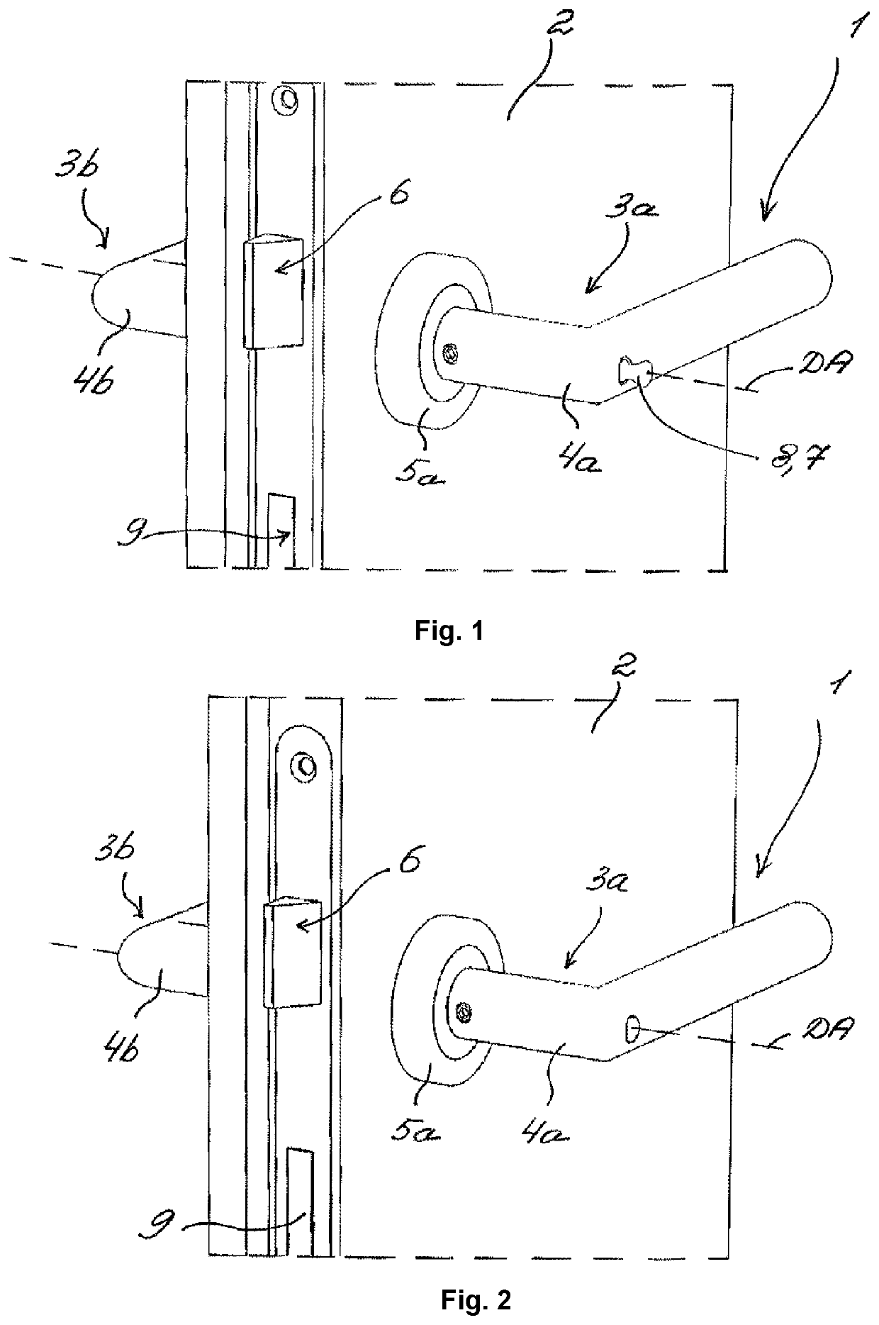
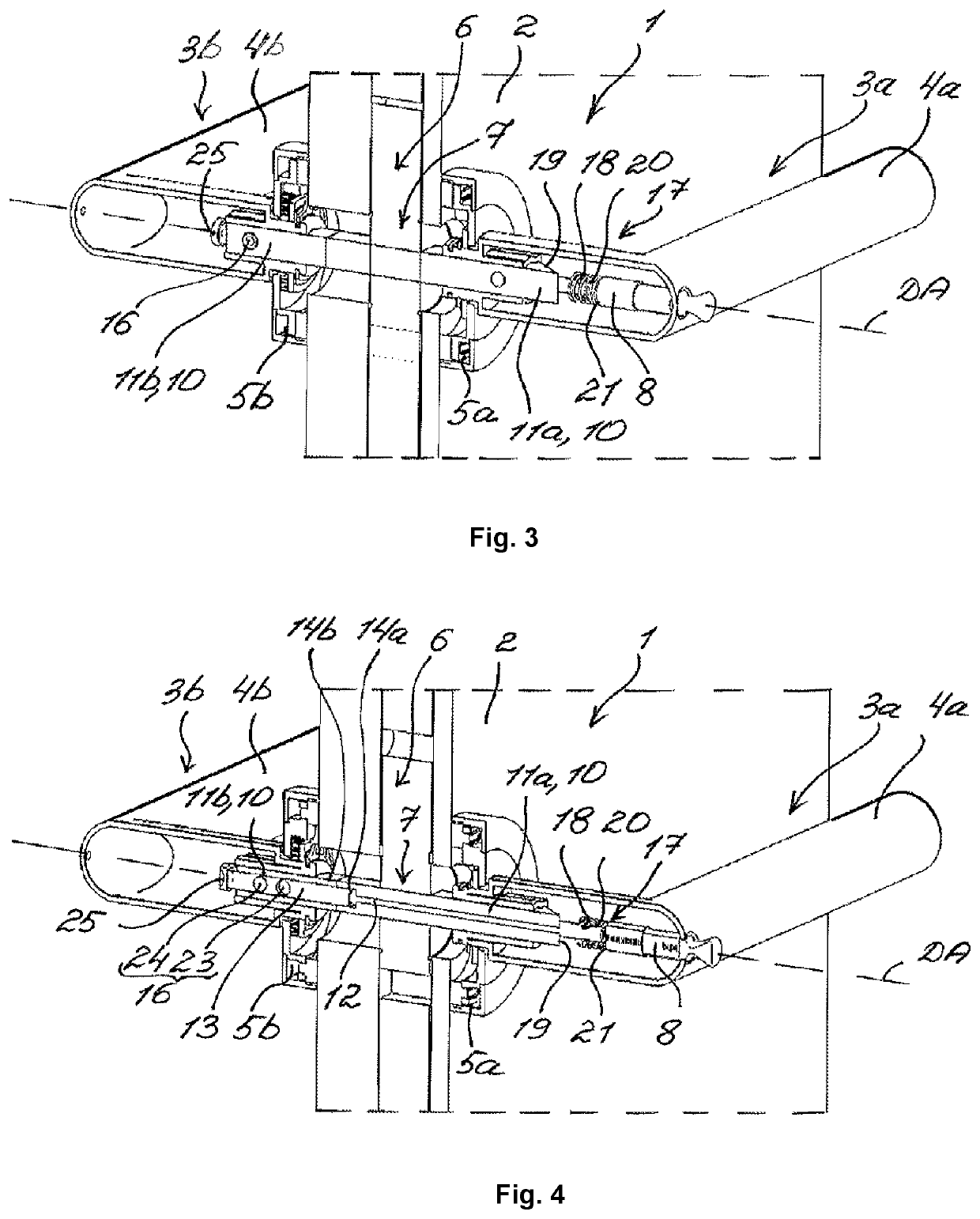
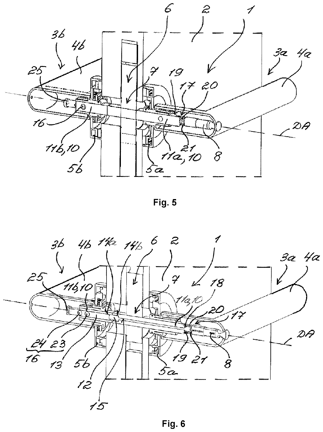
[0030]FIG. 1 and FIG. 2 show views of a door locking system 1 according to the invention. The door locking system 1 is mounted on a door 2 and comprises a first door handle unit 3a and a second door handle unit 3b. The first door handle unit 3a comprises a first door handle 4a and a first cover unit 5a which fixes the door handle 4a to the door 2 so as to be pivotable about a pivot axis DA. The second door handle unit 3b comprises a second door handle 4b and a second cover unit 5b —shown in FIGS. 3-6, —which fixes the door handle 4b to the door 2 so as to be pivotable about the pivot axis DA. The door locking system 1 further comprises a door lock 6 which can be opened by pivoting the door handles 4a and 4b about the pivot axis DA. The door handle units 3a and 3b are coupled to each other via a coupling device 7 with a coupling pin 8. In FIG. 1, the coupling pin 8 is shifted into a decoupling position and in FIG. 2 it is shifted axially relative to the pivot axis DA into a coupling ...


PUM


Abstract

A door locking system for opening and closing a door lock in a door. The door locking system includes a first door handle unit with a first door handle and a second door handle unit with a second door handle. The first door handle and the second door handle are pivotable about a common pivot axis. The door locking system comprises a coupling device with an axially aligned polygonal pin which has two pin pieces. The respective pin piece is connected to the respective door handle in a pivotably fixed manner.

Description

CROSS-REFERENCE TO RELATED PATENT APPLICATIONS[0001]This patent application claims the benefit of priority to German Patent Application No. 10 2020 201 152.4, filed Jan. 30, 2020, the entire teachings and disclosures of the application are incorporated herein by reference thereto.FIELD[0002]The invention relates to a door locking system for opening and closing a door lock in a door according to the preamble of claim 1.BACKGROUND OF THE INVENTION[0003]A door locking system usually comprises a first door handle unit with a first door handle and a second door handle unit with a second door handle. In this case, the door handles are arranged on both sides of the door and are connected to each other in a pivotably fixed manner via a polygonal pin. As a result, the door handles can be pivoted together on the door. The polygonal pin is effectively connected here to a door lock so that when one of the door handles is pivoted, the closed door lock can be opened. In addition to the door locki...

Claims


Application Information

Patent Timeline
Patent Type & Authority Applications(United States)
IPC IPC(8): E05B13/00E05B1/00
CPCE05B13/004E05B1/003E05B15/0033E05B63/16E05B13/101E05B15/006E05B65/0035E05B63/0069
Inventor BOYD, MICHAELUKA, FATOS
Owner KARCHER
Why Eureka
Try Eureka