
Hiding latency in wireless virtual and augmented reality systems

a technology of virtual reality and hidden latency, applied in static indicating devices, instruments, sport apparatus, etc., can solve problems such as inaccurate location of scenery being rendered in the frame, fluctuation of rendering time, and late delivery of rendered frames for presentation

Inactive Publication Date: 2021-08-05
ATI TECH INC
View PDF1 Cites 4 Cited by
  • Summary
  • Abstract
  • Description
  • Claims
  • Application Information

AI Technical Summary

Benefits of technology

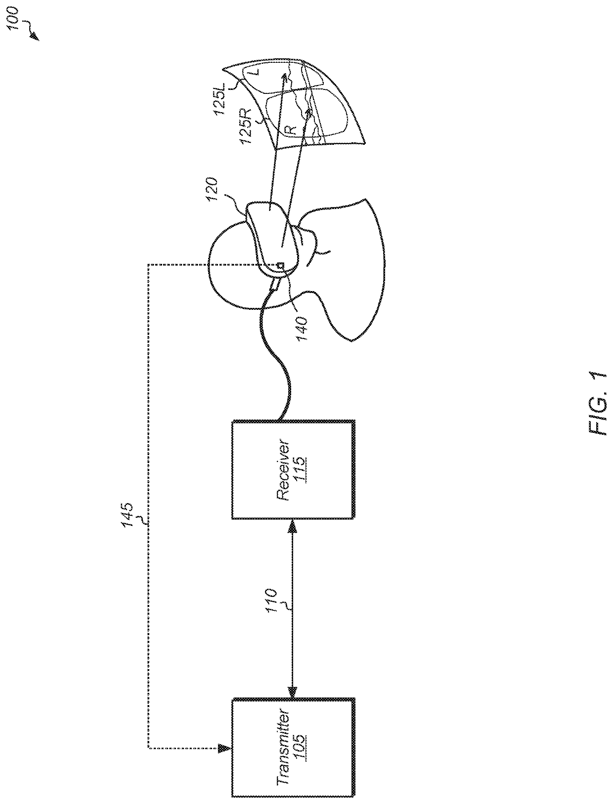
The patent describes a method for reducing latency in virtual and augmented reality applications. The method involves measuring the time it takes for a video frame to be delivered from the rendering unit to the user's head-mounted display and predicting the future head position of the user based on this information. The system then adjusts the frame to match the predicted head position, resulting in a smoother and more immersive experience for the user. The method can be implemented using wireless VR / AR systems and can hide the latency introduced by the system. Overall, the method improves the user's experience and reduces the time it takes to render and display the video frames.

Problems solved by technology

However, rendering time may fluctuate depending on the complexity of the scene, occasionally resulting in a rendered frame being delivered late for presentation.
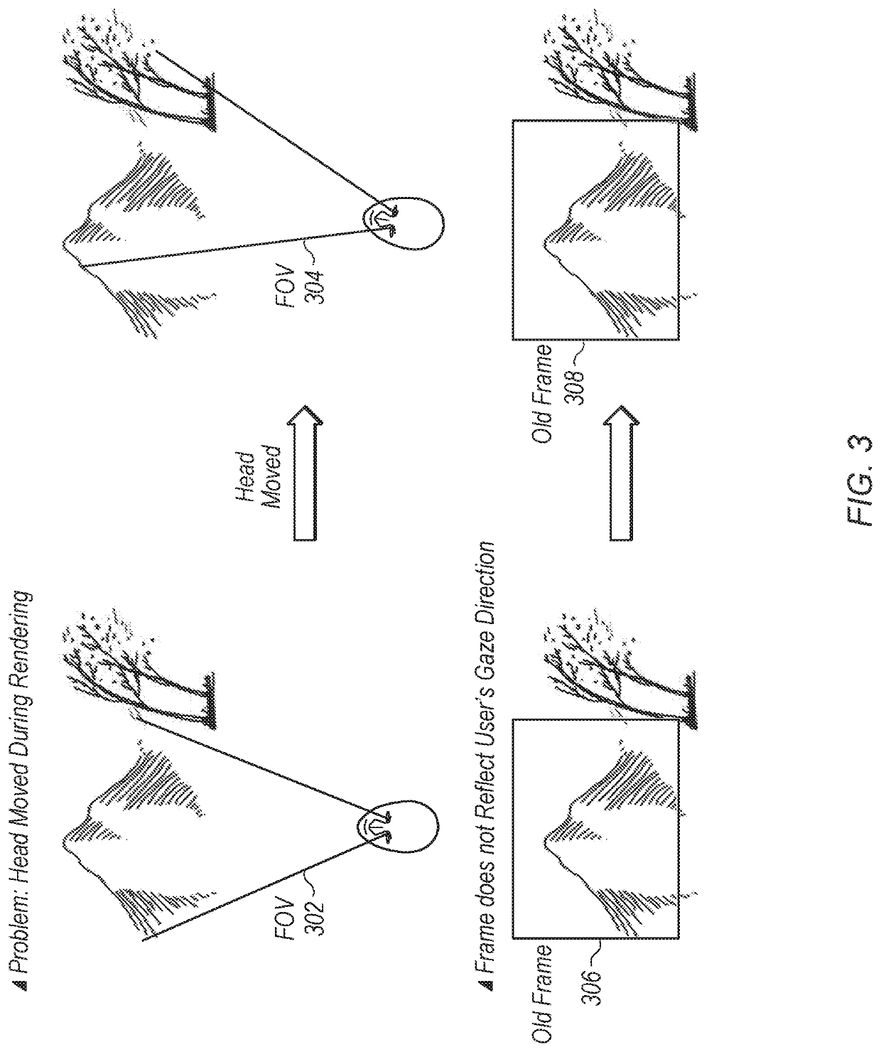
For example, while the system is rendering a frame, the user can move their head, causing the locations of the scenery being rendered in the frame to be inaccurate based on the user's new head pose.
Wireless VR / AR systems typically introduce an additional latency compared to wired systems.
Without special techniques to hide this additional latency, the images presented in the HMD will judder and lag in case of head movements, breaking immersion and causing nausea and eye strain.

Method used


Image

  • Hiding latency in wireless virtual and augmented reality systems
  • Hiding latency in wireless virtual and augmented reality systems
  • Hiding latency in wireless virtual and augmented reality systems

Examples


Embodiment Construction

[0015]In the following description, numerous specific details are set forth to provide a thorough understanding of the methods and mechanisms presented herein. However, one having ordinary skill in the art should recognize that the various implementations may be practiced without these specific details. In some instances, well-known structures, components, signals, computer program instructions, and techniques have not been shown in detail to avoid obscuring the approaches described herein. It will be appreciated that for simplicity and clarity of illustration, elements shown in the figures have not necessarily been drawn to scale. For example, the dimensions of some of the elements may be exaggerated relative to other elements.

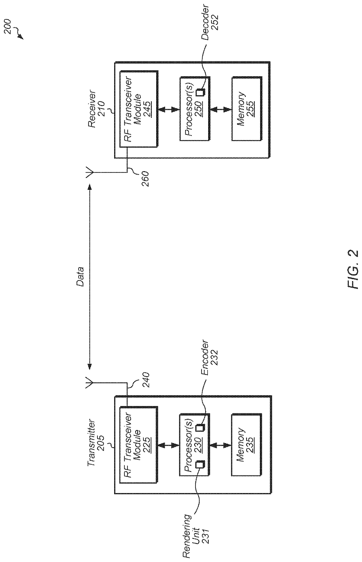
[0016]Various systems, apparatuses, methods, and computer-readable mediums for hiding latency for wireless virtual and augmented reality applications are disclosed herein. In one implementation, a virtual reality (VR) or augmented reality (AR) system includes...


PUM


Abstract

Systems, apparatuses, and methods for hiding latency for wireless virtual reality (VR) and augmented reality (AR) applications are disclosed. A wireless VR or AR system includes a transmitter rendering, encoding, and sending video frames to a receiver coupled to a head-mounted display (HMD). In one scenario, the receiver measures a total latency required for the system to render a frame and prepare the frame for display. The receiver predicts a future head pose of a user based on the total latency. Next, a rendering unit at the transmitter renders, based on the predicted future head pose, a new frame with a rendered field of view (FOV) larger than a FOV of the headset. The receiver rotates the new frame by an amount determined by the difference between the actual head pose and the predicted future head pose to generate a rotated version of the new frame for display.

Description

BACKGROUNDDescription of the Related Art[0001]In order to create an immersive environment for the user, virtual reality (VR) and augmented reality (AR) video streaming applications typically require high resolution and high frame-rates, which equates to high data-rates. For VR and AR headsets or head mounted displays (HMDs), rendering at high and consistent frame rates provides a smooth and immersive experience. However, rendering time may fluctuate depending on the complexity of the scene, occasionally resulting in a rendered frame being delivered late for presentation. Additionally, as the user changes their orientation within a VR or AR scene, the rendering unit will change the perspective from which the scene is rendered.[0002]In many cases, the user can perceive a lag between their movement and the corresponding update to the image presented on the display. This lag is caused by the latency inherent in the system, with the latency referring to the time between when a movement o...

Claims


Application Information

Patent Timeline
Patent Type & Authority Applications(United States)
IPC IPC(8): G06F3/01G06T19/00G02B27/01G06F3/14H04N19/463H04N19/61
CPCG06F3/012G06T19/006G02B27/017G02B2027/0187H04N19/463H04N19/61G06F3/14G06F3/011G09G2354/00G09G2340/16G09G3/001A63F2300/8082A63F13/5255G09G2320/028G09G2320/068
Inventor MIRONOV, MIKHAILKOLESNIK, GENNADIYSINIAVINE, PAVEL
Owner ATI TECH INC
Learn More