Control arm assembly mechanism and control arm assembly method

a technology of control arm and assembly mechanism, which is applied in the direction of metal-working apparatus, vehicle components, metal-working apparatus, etc., can solve the problems of time-consuming and complicated prior art, and achieve the effect of speeding up and simplifying the assembly of the control arm

Inactive Publication Date: 2021-08-12
SHIH HSIANG AUTO PARTS CO LTD
View PDF0 Cites 0 Cited by
  • Summary
  • Abstract
  • Description
  • Claims
  • Application Information

AI Technical Summary

Benefits of technology

[0003]It is an objective of the present disclosure to provide an assembly mechanis

Problems solved by technology

However, the prior art is not only complicated but also

Method used


Image

  • Control arm assembly mechanism and control arm assembly method
  • Control arm assembly mechanism and control arm assembly method
  • Control arm assembly mechanism and control arm assembly method

Examples


Embodiment Construction

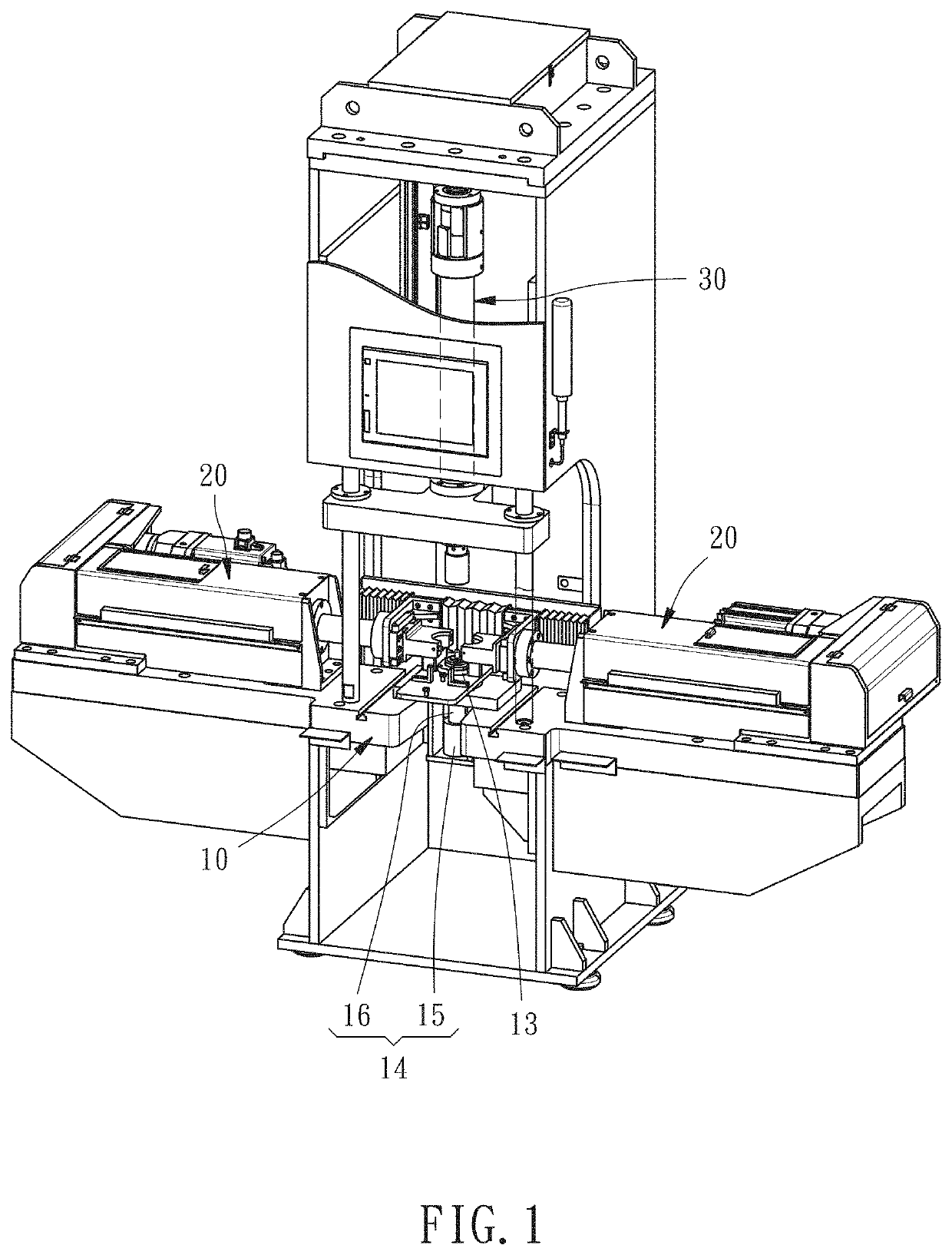
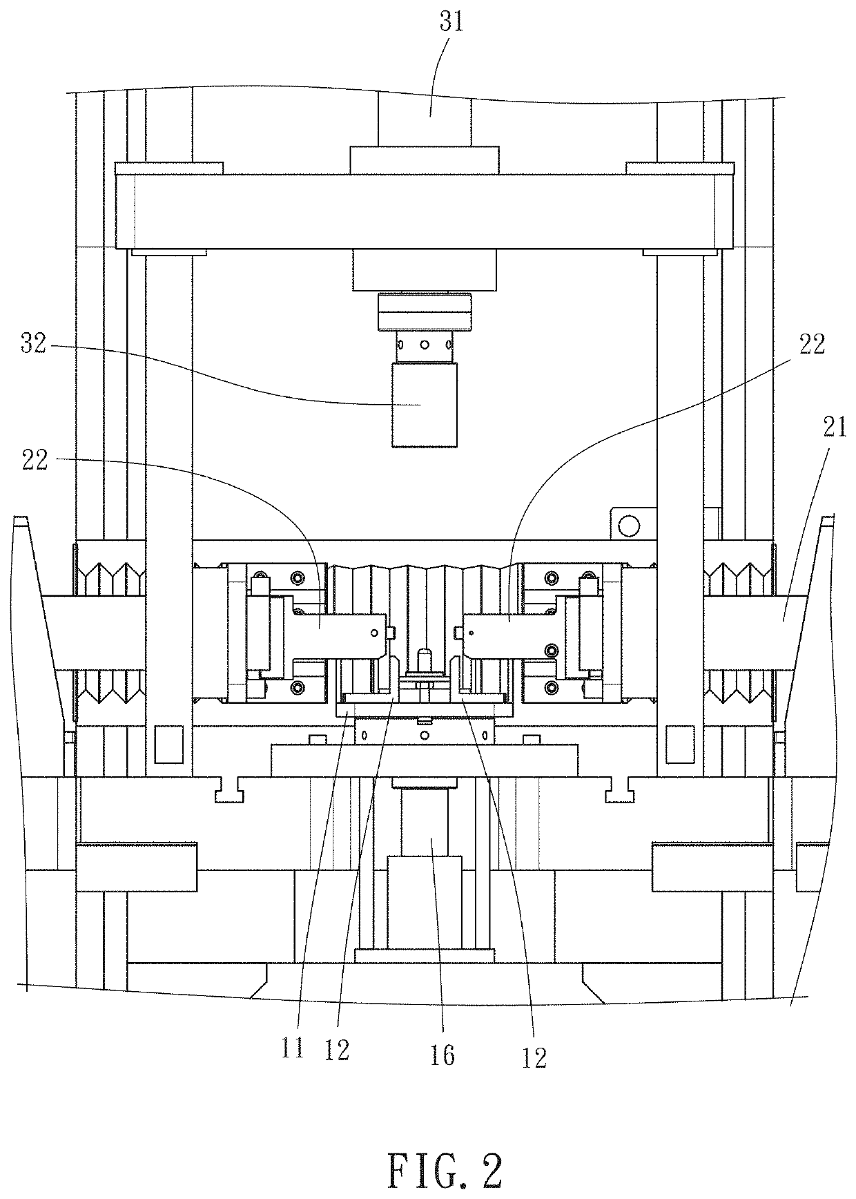
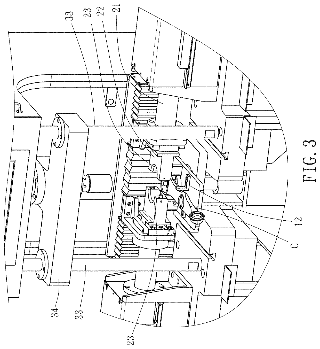
[0015]The technical features of the present disclosure as described herein are not limited to specific structures, purposes and applications of the embodiments of the present disclosure. All technical terms used herein are exemplary, descriptive terms comprehensible to persons skilled in the art. Directional expressions used herein, such as “front,”“upward,”“downward,”“backward,”“leftward,”“rightward,”“top,”“bottom,”“in” and “outer,” are exemplary, descriptive terms which must be interpreted from a layman's perspective and must not be restrictive of the appended claims of the present disclosure.

[0016]Singular quantitative wording used in the appended claims of the present disclosure, such as “a,”“an,”“one” and “the,” must be interpreted in such a manner to include their plural forms. For example, the expression “a component” must be interpreted in such a manner to mean “one or more components” and include equivalent substitutes well-known among persons skilled in the art. All conjun...


PUM


Abstract

A control arm assembly mechanism includes: a workbench having thereon a holder; a vertically pressing device disposed above the workbench and including a moving arm capable of moving toward and away from the holder; and two transversely pressing devices flanking the workbench and each including a moving arm capable of moving toward and away from the holder. The control arm assembly mechanism operates in such a manner to compress transversely and vertically a bushing placed on the workbench and thereby fit the bushing into a control arm.

Description

BACKGROUND OF THE INVENTION1. Field of the Invention[0001]The present disclosure relates to production of control arms for use in car suspension systems and, more particularly, to a control arm assembly mechanism and a control arm assembly method.2. Description of the Related Art[0002]Conventional control arms are important components in a car suspension system. The control arms vary in length, size and form, depending on automobile manufacturers, makes and models; however, every control arm comprises a metallic arm and a bushing. According to prior art, the metallic arm and the bushing are separately manufactured, and then the bushing is squeezed into a through hole at one end of the metallic arm by a conventional hydraulic or pneumatic stamping process. According to the prior art, the bushing is squeezed into a transitional jig by a first-instance compression process which is intended to reduce the outer diameter of the bushing in order for the bushing to be restrained by the jig....

Claims


Application Information

Patent Timeline
IPC IPC(8): B23P19/02B23P19/00B23P19/04
CPCB23P19/02B23P19/04B23P19/006B23P19/027B23P2700/14B60G2206/11B60G2206/80B60G2206/82092B60G2206/91B60G2206/92
Inventor CHOU, CHE-HUNGCHOU, KUN-LIANG
Owner SHIH HSIANG AUTO PARTS CO LTD
Why Eureka
Try Eureka