Heat transfer plate and gasket

a technology of heat transfer plate and gasket, which is applied in the direction of indirect heat exchanger, lighting and heating apparatus, laminated elements, etc., can solve the problems of fibers and particles from the fluid flowing through the phe getting caught between the heat transfer plate and and the contact with the adjacent heat transfer plate may be very limited, so as to achieve the effect of more area efficient heat transfer pla

Active Publication Date: 2021-08-12
ALFA LAVAL CORP AB
View PDF0 Cites 0 Cited by
  • Summary
  • Abstract
  • Description
  • Claims
  • Application Information

AI Technical Summary

Benefits of technology

[0021]As said above, the first inner port portion of the heat transfer plate comprises a number of first support projections along the second section of the first inner edge, and a first top portion of these first support projections extends in the first plane. This means that the first support projections of the heat transfer plate, when this is arranged properly in a PHE between two adjacent heat transfer plates according to the invention, may abut respective support projections of the adjacent heat transfer plate facing the front side of the heat transfer plate in question. Further, as said above, the complete first inner port portion of the heat transfer plate except for the first support projections extends, at a distance ≠0 from the first and second planes, i.e. between the first and second planes. This means that the heat transfer plate, when arranged properly in a PHE between two adjacent heat transfer plates according to the invention, may be separated from the adjacent heat transfer plate facing the back side of the heat transfer plate within the complete first inner port portion, and may be separated from the adjacent heat transfer plate facing the front side of the heat transfer plate within the complete first inner port portion except for at the first support projections. Consequently, within the first inner port portion of the heat transfer plate in question, the contact with the adjacent heat transfer plates may be very limited. This means that the risk of fibers and particles from the fluids flowing through the PHE getting caught between the heat transfer plate and the adjacent heat transfer plates may be relatively very small. This is a huge advantage, especially in sanitary or hygienic applications. Also, this means that the front and back gasket grooves may be allowed to extend close to the first inner edge, which may make the heat transfer plate more area efficient.
[0060]The gasket may be so designed that an inner surface of the inner gasket portion extending between the front and back sides of the gasket is convex, i.e. bulging outwards, along at least a part of the second section of the inner edge. Such a rounded inner surface of the gasket may facilitate the entrance of the fluids flowing through the PHE into the channels between the heat transfer plates and prevent that fibers and particles from the fluids get caught at the gasket.

Problems solved by technology

This will result in empty gaps between the heat transfer plates.
This may be a problem, especially in sanitary or hygienic applications.
Consequently, within the first inner port portion of the heat transfer plate in question, the contact with the adjacent heat transfer plates may be very limited.
This means that the risk of fibers and particles from the fluids flowing through the PHE getting caught between the heat transfer plate and the adjacent heat transfer plates may be relatively very small.
Consequently, within the second inner port portion of the heat transfer plate in question, the contact with the adjacent heat transfer plates may be very limited.
This means that the risk of fibers and particles from the fluids flowing through the PHE getting caught between the heat transfer plate and the adjacent heat transfer plates may be relatively very small.

Method used


Image

  • Heat transfer plate and gasket
  • Heat transfer plate and gasket
  • Heat transfer plate and gasket

Examples


Embodiment Construction

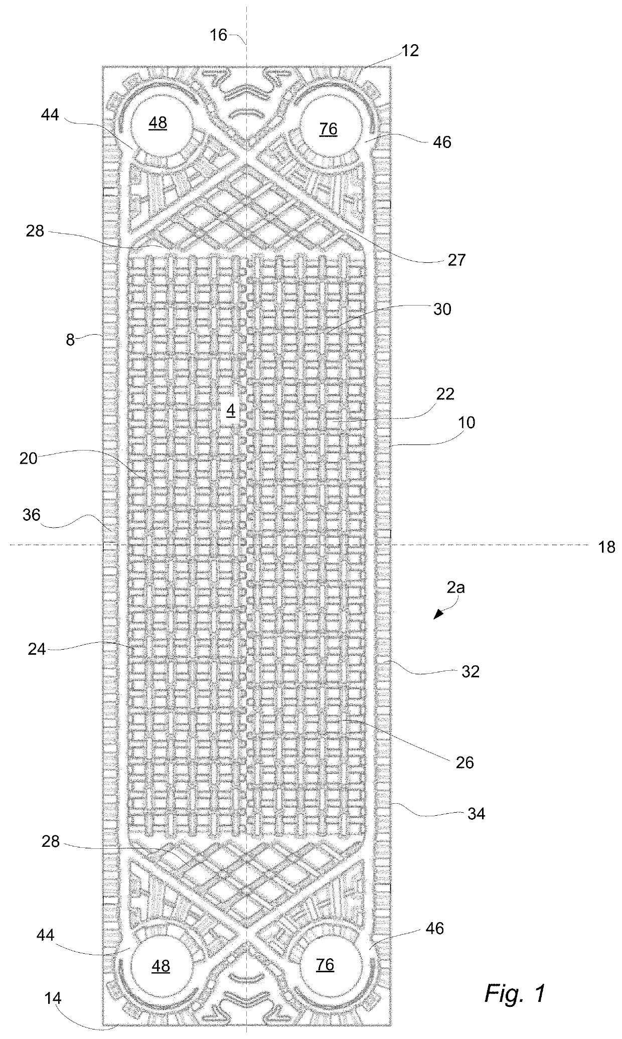
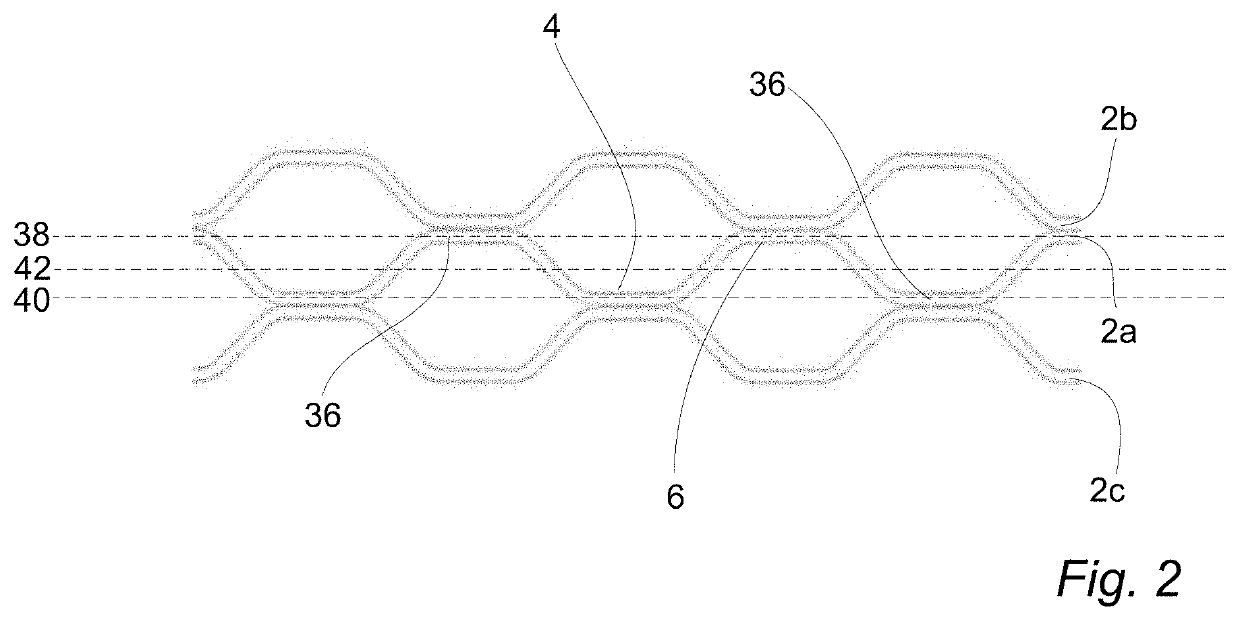
lass="d_n">[0089]FIG. 1 shows a heat transfer plate 2a of a gasketed plate heat exchanger as described by way of introduction. The gasketed PHE, which is not illustrated in full, comprises a pack of heat transfer plates 2 like the heat transfer plate 2a, i.e. a pack of similar heat transfer plates, separated by gaskets, which also are similar and which will be described in further detail below. In the plate pack, the heat transfer plates, which each has a front side 4 (illustrated in FIG. 1) and a back side 6 (not visible in FIG. 1 but indicated in FIG. 2), are arranged with the front side 4 of one heat transfer plate facing the front side 4 of a neighboring heat transfer plate, and every second heat transfer plate turned upside-down in relation to a reference orientation (illustrated in FIG. 1).

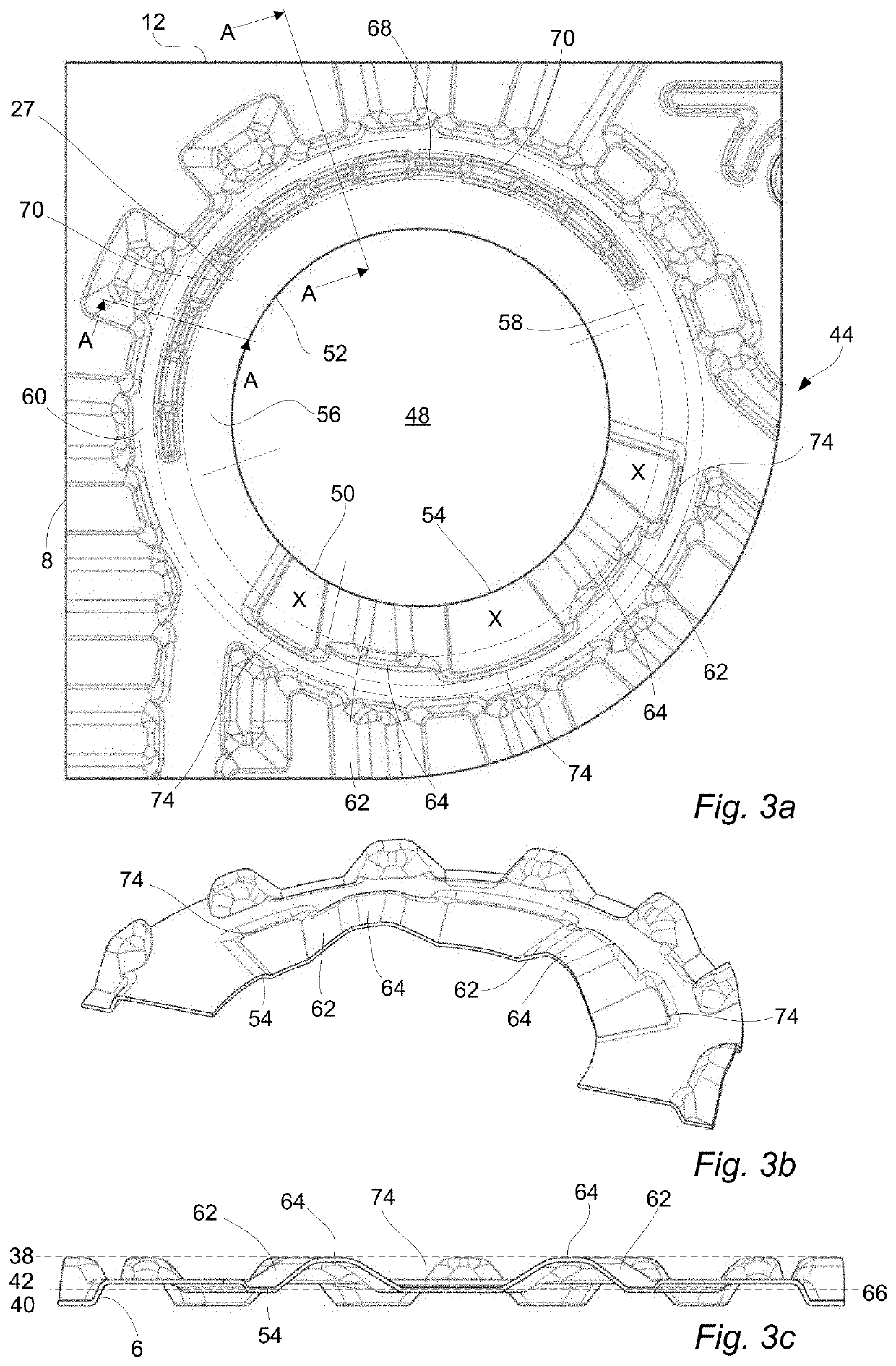
[0090]The heat transfer plate 2a is an essentially rectangular sheet of stainless steel. It comprises two opposing long sides 8, 10 and two opposing short sides 12, 14. The heat transfer pla...


PUM


Abstract

A heat transfer plate comprises at least one first port hole area and opposing front and back sides, first and second planes defining the extension of the plate. Each first port hole area comprises a first port hole defined by an annular first inner edge of the plate, with the first inner edge consisting of first and second sections. Each first port hole area further comprises an annular first inner port portion extending along the first and second sections. The first inner port portion comprises, as seen from the front side of the plate, a number ≥1 of first support projections along the second section of the first inner edge, each first support projections comprising a first top portion extending in the first plane. The plate extends, within the first inner port portion and outside first support projections, at a distance ≠0 from the first and second planes.

Description

TECHNICAL FIELD[0001]The invention relates to a heat transfer plate comprising at least one port hole area comprising a port hole defined by an annular inner edge of the heat transfer plate, wherein a gasket groove on one side of the heat transfer plate extends completely around the port hole and a gasket groove on the other side of the heat transfer plate extends only partly around the port hole. The invention also relates to a gasket for sealing between two adjacent heat transfer plates in a plate heat exchanger, which gasket comprises at least one annular gasket part arranged to seal around two overlapping port holes in the heat transfer plates.BACKGROUND ART[0002]Plate heat exchangers, PHEs, typically consist of two end plates in between which a number of heat transfer plates are arranged in an aligned manner, i.e. in a stack or pack. The heat transfer plates of a PHE may be of the same or different types and they may be stacked in different ways. In some PHEs, the heat transfer...

Claims


Application Information

Patent Timeline
Patent Type & Authority Applications(United States)
IPC IPC(8): F28D9/00F28F3/04F28F3/10
CPCF28D9/005F28F3/10F28F3/046F28F3/086
Inventor BLOMGREN, FREDRIK
Owner ALFA LAVAL CORP AB
Why Eureka
Try Eureka