
Self-timed timer

a self-timer and timer technology, applied in the field of asynchronous state machines, can solve the problems of erroneous state changes, difficulty in design, irregular timing of state changes in asynchronous state machines, etc., and achieve the effect of low cos

Inactive Publication Date: 2014-04-08
SCHOBER RICHARD L
View PDF8 Cites 0 Cited by
  • Summary
  • Abstract
  • Description
  • Claims
  • Application Information

AI Technical Summary

Benefits of technology

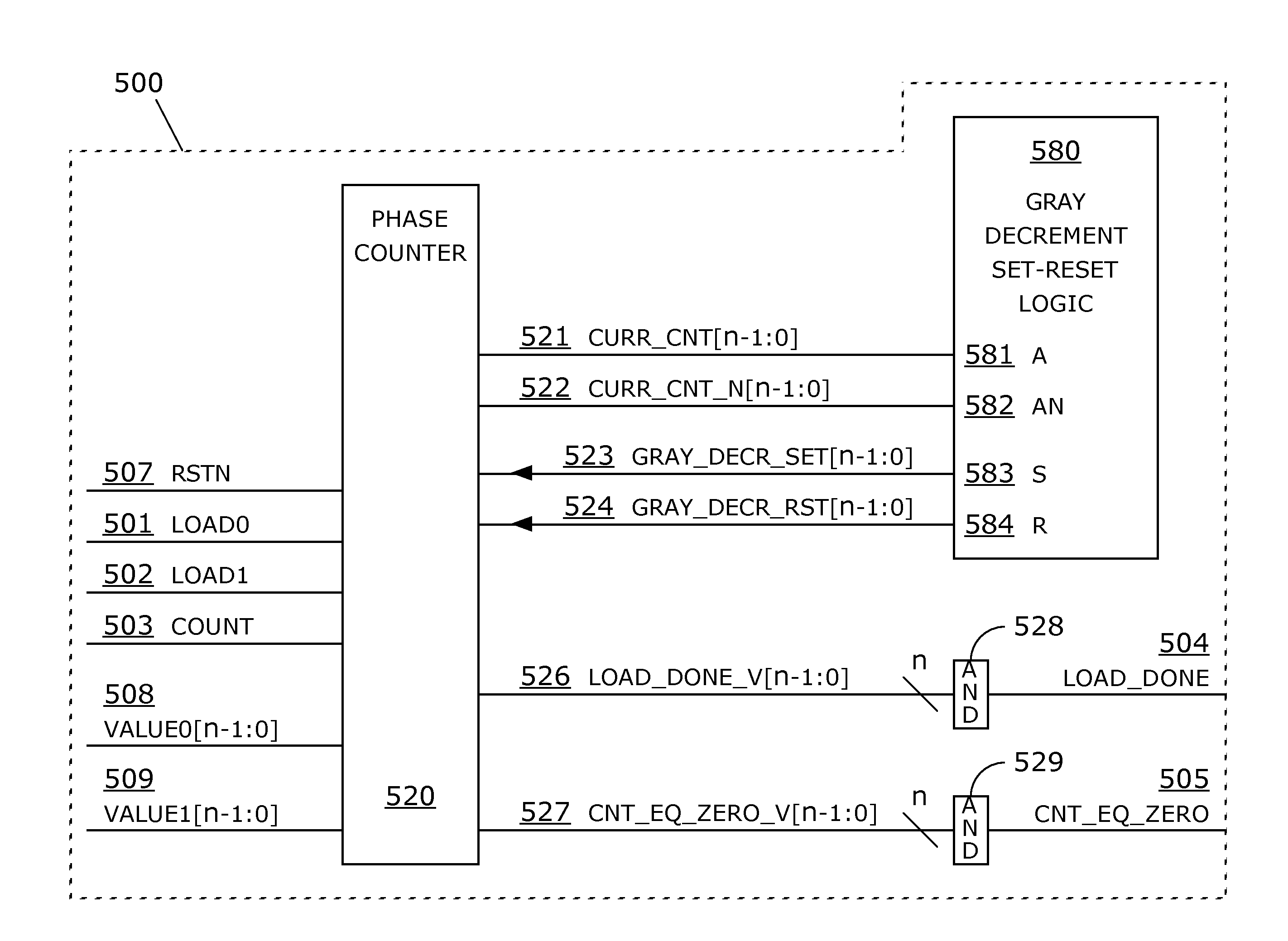
The present invention provides a self-timed timer that can measure time intervals over a wide range of time ranges and is cost-effective to design and implement. The timer comprises an asynchronous state machine with a pulse timer and a pulse sequencer that can operate over a wide range of pulse intervals and widths. This invention offers a more efficient and cost-effective solution for time measurement compared to hybrid and synchronous timers that require an external clock circuit.

Problems solved by technology

While asynchronous circuits can have speed and power advantages over synchronous circuits, they are difficult to design.
In contrast, the timing of state changes in asynchronous state machines may be irregular, based on variable combinatorial logic delays.
Furthermore, asynchronous state machines are susceptible to multi-path delays that can cause signal glitches, which in turn may cause erroneous state changes.
Consequently, timing characteristics of delays, pulses and clocks produced by digital asynchronous timers are imprecise and variable.
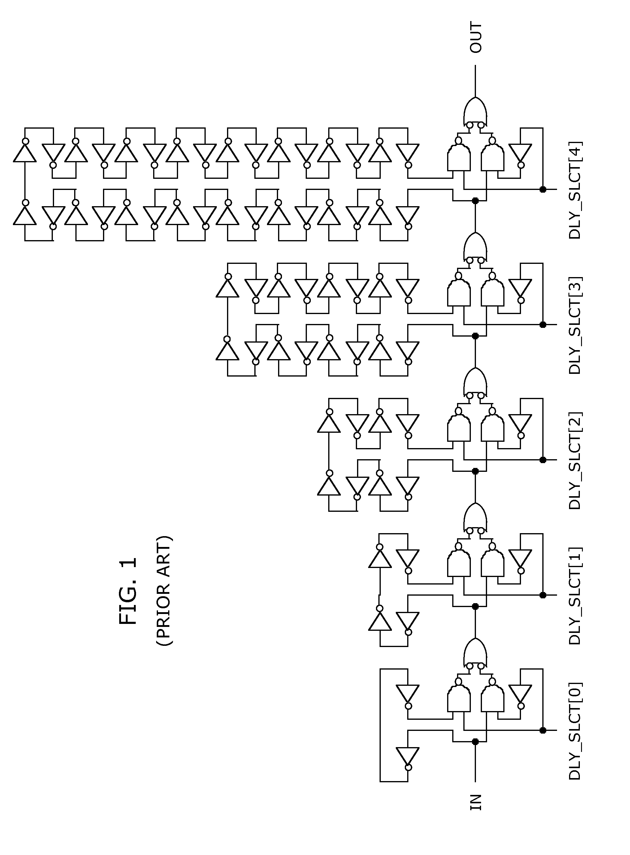
Digital delay lines are useful for small delays, but they may not scale well because delay is a linear function of the number of logic gates in the gate chain.
Hence, implementing a long-duration time interval with a digital delay line consumes a lot of space and thus is costly.
Long oscillation periods may require large gate chains and may be costly.
The hybrid timer of U.S. Pat. No. 7,071,751 is time consuming and costly to construct owing to the disparate nature of each of its three sub-components.
Furthermore, programming the hybrid timer is complicated by the need to set a different parameter for each of its three sub-components.

Method used


Image

  • Self-timed timer
  • Self-timed timer
  • Self-timed timer

Examples


Embodiment Construction

[0054]In the following description, numerous specific details are set forth to provide a thorough understanding of the present invention. However, it will be apparent to one of ordinary skill in the art that the invention may be practiced without these particular details. In other instances, methods, procedures, and components that are well known to those of ordinary skill in the art are not described in detail to avoid obscuring aspects of the present invention.

[0055]In digital logic, an asynchronous state machine (ASM) has much in common with an ordinary synchronous state machine. Both may have (1) storage elements, e.g. latches or flip-flops, which hold a current state; (2) deterministic state transitions based on combinatorial functions of current state and external input signals; and (3) output signals that are combinatorial functions of current state and input signals. Additionally, both may have an external reset input that forces the state machine to a start state. There is,...


PUM


Abstract

The present invention discloses a digital self-timed timer for measuring the passage of time; a digital self-timed pulse generator for generating both continuous and finite pulse sequences; and a digital self-timed data receiver for recovering data from an asynchronous, two-wire bit-channel. Being self-timed, a disclosed self-timed timer measures time as a function of logic delays incurred while executing a sequence of internal state transitions. A pulse generator supports both a triggered pulse mode and continuous clock generation; pulse widths and pulse intervals are programmable. A data receiver may recover a data bit from each received two-bit code word and outputs recovered data and an associated write strobe for each recovered datum.

Description

CROSS-REFERENCE TO RELATED PUBLICATIONS[0001]Information providing background and explanation to the instant invention is found in the following publications. U.S. Pat. No. 7,071,751, Kaviani; U.S. Pat. No. 7,190,756, Kaviani et al.; U.S. Pat. No. 7,477,112, Pi et al. Additional references include: Richard L. Schober, “Asynchronous State Machine Design Handbook”, November 2011; Richard F. Tinder, “Asynchronous Sequential Machine Design and Analysis: A Comprehensive Development of the Design and Analysis of Clock-Independent State Machines and Systems”, Morgan & Claypool Publishers, 2009. The following lecture notes, include information on the nature and treatment of glitches in digital logic: John Knight, “Glitches and Hazards in Digital Circuits”, Electronics Department, Carleton University, Mar. 24, 2004; www.doe.carleton.ca / ˜jknight / 97.267 / 267—04W / Asch1HazShorapdf [Jul. 22, 2011]. The referenced patents, articles and notes are incorporated herein in their entirety by reference.BA...

Claims


Application Information

Patent Timeline
IPC IPC(8): H04L25/38
CPCG04F10/02H04L25/38
Inventor SCHOBER, RICHARD, L.
Owner SCHOBER RICHARD L
Learn More