Treatment element for a treatment element shaft of a screw machine, and method for producing a treatment element

a technology of treatment element and screw machine, which is applied in the direction of metal working equipment, metal-working tools, metal-working apparatus, etc., can solve the problems of increasing the tendency for wear and tear

Pending Publication Date: 2021-08-19
COPERION GBMH
View PDF4 Cites 0 Cited by
  • Summary
  • Abstract
  • Description
  • Claims
  • Application Information

AI Technical Summary

Benefits of technology

[0004]The invention is based on an object of creating an improved treatment element for a treatment element shaft of a screw machine, which treatment element is particularly

Problems solved by technology

The sealingly meshing design of the treatment elements has an influence on the conveying

Method used


Image

  • Treatment element for a treatment element shaft of a screw machine, and method for producing a treatment element
  • Treatment element for a treatment element shaft of a screw machine, and method for producing a treatment element
  • Treatment element for a treatment element shaft of a screw machine, and method for producing a treatment element

Examples


Embodiment Construction

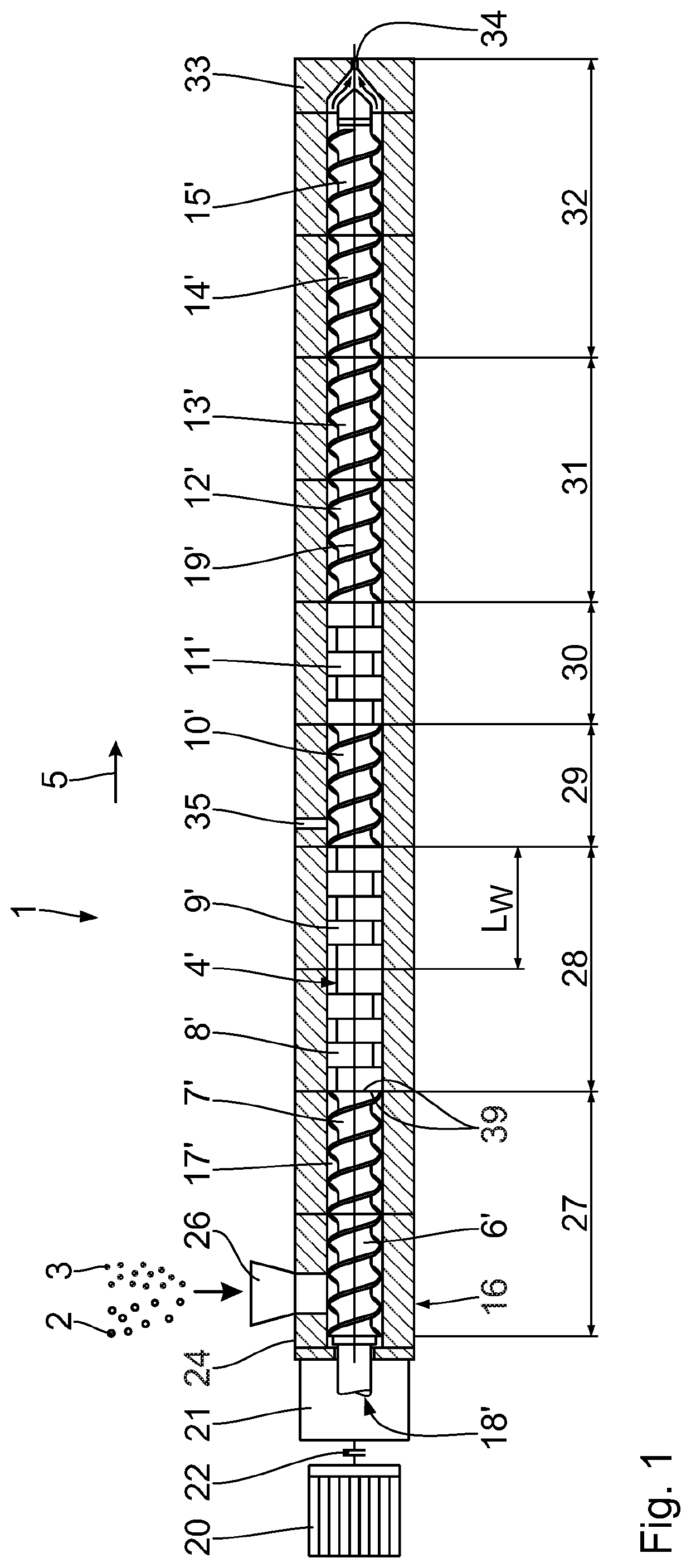
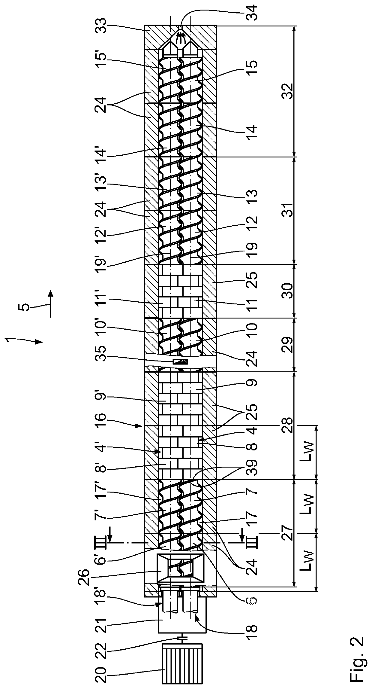
[0054]A screw machine 1 for the preparation of a substance or plastics material 2 will be described on the basis of FIG. 1 to FIG. 3. The plastics material may comprise additives 3. The screw machine 1 is in the form of a multi-shaft screw machine, in particular in the form of a two-shaft screw machine.

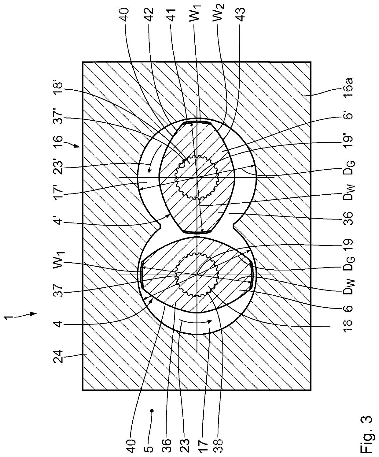
[0055]The screw machine 1 has a first treatment element shaft 4 and a second treatment element shaft 4′. To distinguish between the components of the first treatment element shaft 4 and of the second treatment element shaft 4′, the reference designations relating to the second treatment element shaft 4′ have the suffix ‘. Along a conveying direction 5, the treatment element shafts 4, 4’ each comprise multiple treatment elements 6 to 15 or 6′ to 15′ respectively, which are arranged in series. The treatment element shafts 4, 4′ are arranged rotatably in a housing 16 of the screw machine 1. The housing 16 comprises a housing main body 16a. In the housing main body 16a, there are arranged...


PUM

PropertyMeasurementUnit
Angleaaaaaaaaaa
Vickers hardnessaaaaaaaaaa

Abstract

A treatment element for a treatment element shaft of a screw machine comprises a main body with an outer wall, wherein the outer wall has a first wall section and a second wall section and wherein the first wall section is harder than the second wall section.

Description

CROSS-REFERENCES TO RELATED APPLICATIONS[0001]This application claims the priority of German Patent Application, Serial No. DE 10 2020 201 895.2, filed Feb. 17, 2020, the content of which is incorporated herein by reference in its entirety as if fully set forth herein.FIELD OF THE INVENTION[0002]The invention relates to a treatment element for a treatment element shaft of a screw machine. The invention furthermore relates to a treatment element shaft having a treatment element of said type and to a screw machine having a treatment element shaft of said type. The invention also relates to a method for producing a treatment element for a treatment element shaft of a screw machine.BACKGROUND OF THE INVENTION[0003]WO 2018 / 033 353 A1 has disclosed a multi-shaft screw machine comprising a housing main body with two housing bores and comprising two treatment element shafts arranged in the housing bores. The treatment element shafts each comprise multiple treatment elements in the form of s...

Claims


Application Information

Patent Timeline
IPC IPC(8): B29C48/40B29C48/395B29C48/57B29C48/56
CPCB29C48/402B29C48/56B29C48/57B29C48/397B23P19/06B29C48/767
Inventor POLZER, KARL-CONRAD
Owner COPERION GBMH
Why Eureka
Try Eureka