Ultrasonic tonometer

a tonometer and ultrasonic technology, applied in the field of ultrasonic tonometers, can solve the problems that the cornea of the examinee's eye cannot be properly irradiated with ultrasonic waves, the ultrasonic wave at such a level that the cornea is flattened or depressed cannot be applied to the examinee's eye, and the burden on the patient can be reduced, so as to achieve the effect of reducing the burden on the patient and reducing the accuracy of eye pressur

Pending Publication Date: 2021-08-26
NIDEK CO LTD
View PDF0 Cites 0 Cited by
  • Summary
  • Abstract
  • Description
  • Claims
  • Application Information

AI Technical Summary

Benefits of technology

[0008]There are also other problems. In an ultrasonic type (an acoustic radiation pressure type), a cornea can be deformed in a short period of time, and therefore, there is an advantage that eye pressure measurement can be performed in a short period of time and a burden on a patient can be reduced. However, when the cornea is deformed in a short period of time, a detection signal for detecting a cornea deformation state also rapidly changes. For this reason, influence of, e.g., unexpected noise caused in the detection signal is more likely to be provided, leading to a probability that eye pressure measurement accuracy is degraded.

Problems solved by technology

However, in the typical device, the cornea of the examinee's eye cannot be properly irradiated with the ultrasonic wave.
For example, in the device of Patent Literature 1, the cornea cannot be properly irradiated with the ultrasonic wave, and the ultrasonic wave at such a level that the cornea is flattened or depressed cannot be actually applied to the examinee's eye.
Moreover, in, e.g., the device of Patent Literature 2, the cornea cannot be properly irradiated with the ultrasonic wave, and the characteristics of the reflected wave cannot be sufficiently detected.
There are also other problems.
For this reason, influence of, e.g., unexpected noise caused in the detection signal is more likely to be provided, leading to a probability that eye pressure measurement accuracy is degraded.

Method used


Image

  • Ultrasonic tonometer
  • Ultrasonic tonometer
  • Ultrasonic tonometer

Examples


first embodiment

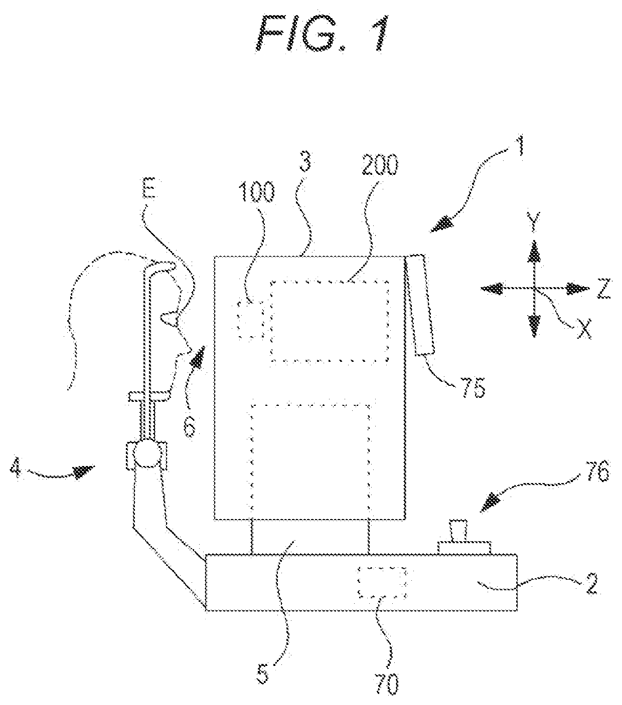
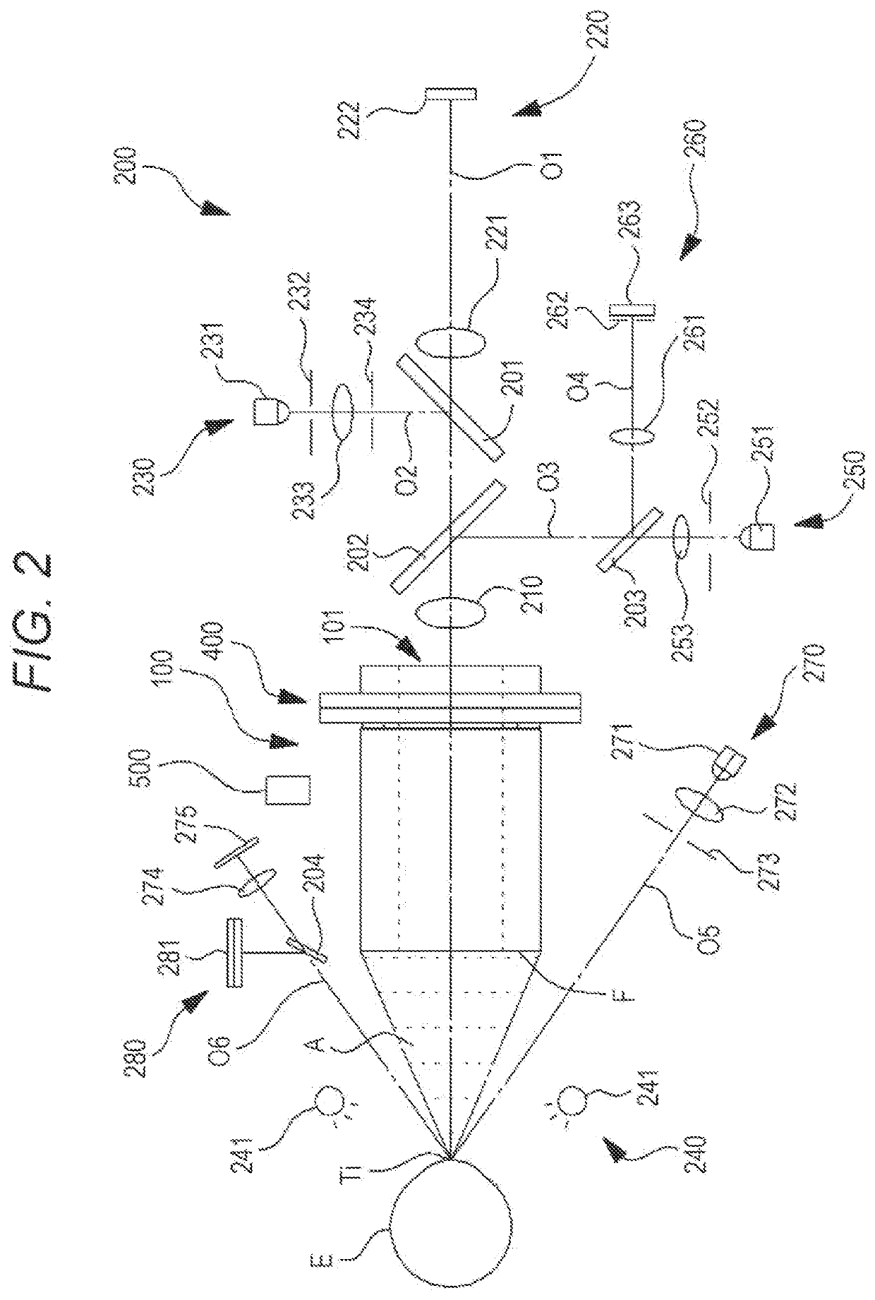
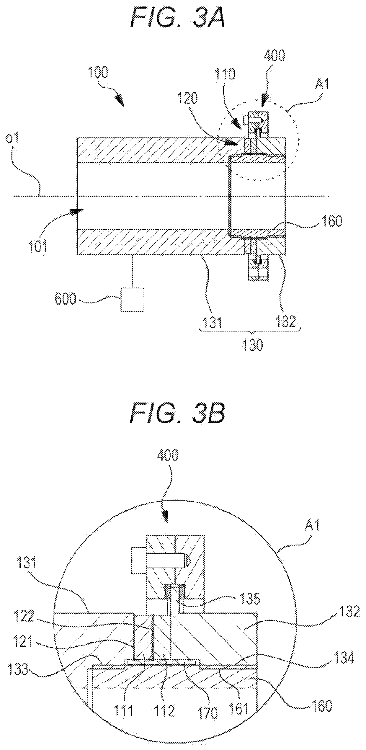
[0038]Hereinafter, a first embodiment according to the present disclosure will be described. An ultrasonic tonometer (e.g., an ultrasonic tonometer 1) of the first embodiment measures the eye pressure of an examinee's eye by means of an ultrasonic wave. The ultrasonic tonometer includes, for example, an ultrasonic actuator (e.g., an ultrasonic actuator 100) and a current adjuster (e.g., a current adjuster 83). The ultrasonic actuator has an ultrasonic element (e.g., an ultrasonic element 110), and irradiates the examinee's eye with the ultrasonic wave. The current adjuster adjusts a current applied to the ultrasonic element. Thus, a sound pressure or an acoustic radiation pressure output from the ultrasonic actuator can be stabilized, and eye pressure measurement can be suitably performed. For example, the ultrasonic tonometer irradiates the examinee's eye with the stable sound pressure or acoustic radiation pressure so that a cornea can be suitably deformed (brought into an applana...

second embodiment

[0042]Hereinafter, a second embodiment according to the present disclosure will be described. An ultrasonic tonometer (e.g., an ultrasonic tonometer 1) of the second embodiment measures the eye pressure of an examinee's eye by means of an ultrasonic wave. The ultrasonic tonometer includes, for example, an irradiator (e.g., an ultrasonic actuator 100) and a controller (e.g., a controller 70). The irradiator has an ultrasonic element (e.g., an ultrasonic element 110), and irradiates the examinee's eye with the ultrasonic wave. The controller controls irradiation to correct an application frequency for the ultrasonic element. With this configuration, a sound pressure (or an acoustic radiation pressure) output to the examinee's eye can be stabilized.

[0043]Note that the controller may correct the application frequency according to a temporal change in the resonant frequency of the irradiator. For example, the controller may correct the application frequency to approach the resonant frequ...

third embodiment

[0049]Hereinafter, a third embodiment according to the present disclosure will be described. An ultrasonic tonometer of the third embodiment measures the eye pressure of an examinee's eye by means of an ultrasonic wave. The ultrasonic tonometer includes, for example, an irradiator (e.g., an ultrasonic actuator 100) and a controller (e.g., a controller 70). The irradiator has an ultrasonic element, and irradiates the examinee's eye with the ultrasonic wave. The controller controls the irradiator. The controller controls the sound pressure or acoustic radiation pressure of the ultrasonic wave output by the irradiator to change eye pressure measurement accuracy. With this configuration, the eye pressure can be measured with suitable measurement accuracy.

[0050]Note that the controller may control the rate (speed) of increase in the sound pressure or the acoustic radiation pressure, thereby changing the eye pressure measurement accuracy. For example, in a case where the eye pressure is m...


PUM


Abstract

An ultrasonic tonometer for measuring the eye pressure of an examinee's eye by means of an ultrasonic wave includes an ultrasonic actuator having an ultrasonic element and configured to irradiate the examinee's eye with the ultrasonic wave, and current adjustment means configured to adjust a current applied to the ultrasonic element to control the sound pressure or acoustic radiation pressure of the ultrasonic wave. With this configuration, the ultrasonic tonometer solving at least one of typical problems can be provided. For example, the ultrasonic tonometer capable of properly irradiating the examinee's eye with the ultrasonic wave can be provided.

Description

TECHNICAL FIELD[0001]The present disclosure relates to an ultrasonic tonometer for measuring the eye pressure of an examinee's eye by means of an ultrasonic wave.BACKGROUND ART[0002]An air-injection tonometer has been still generally known as a non-contact tonometer. The air-injection tonometer detects a cornea deformation state upon injection of air to a cornea and the pressure of air injected to the cornea, thereby converting an air pressure in a predetermined deformation state into an eye pressure.[0003]As the non-contact tonometer, an ultrasonic tonometer for measuring an eye pressure by means of an ultrasonic wave has been proposed (see Patent Literature 1). The ultrasonic tonometer of Patent Literature 1 detects a cornea deformation state upon radiation of a cornea with the ultrasonic wave and the pressure of radiation to the cornea, thereby converting a radiation pressure in a predetermined deformation state into an eye pressure.[0004]As the ultrasonic tonometer, a device con...

Claims


Application Information

Patent Timeline
Patent Type & Authority Applications(United States)
IPC IPC(8): A61B3/16A61B3/00
CPCA61B3/165A61B3/0041
Inventor MIWA, TETSUYUKIUEMURA, TSUTOMUSHIMIZU, KAZUNARI
Owner NIDEK CO LTD
Why Eureka
Try Eureka