Safety truck attachments, and methods of safety truck use

a technology of safety truck and safety truck, which is applied in the direction of pedestrian/occupant safety arrangement, traffic signals, and ways, etc., can solve the problems of increasing the number of vehicles involved, increasing the number of accidents, so as to improve the protection and enhance the protection

Pending Publication Date: 2021-09-02
ROYAL TRUCK & EQUIP INC
View PDF29 Cites 5 Cited by
  • Summary
  • Abstract
  • Description
  • Claims
  • Application Information

AI Technical Summary

Benefits of technology

[0024]The present invention addresses the foregoing and other drawbacks of the prior art by providing both methods and apparatus designed to enhance the protection provided by safety trucks to roadway construction, maintenance and repair personnel working in and near roadway workzones and worksites.
[0025]More particularly, the present invention improves the protection that can be provided by safety trucks to personnel working within and near to roadway workzones and worksites by providing not only 1) new methods of safety truck use, but also 2) more than a dozen new attachments for safety trucks, and 3) many new connection points where the new attachments can be interchangeably coupled to safety trucks.
[0026]As a direct result of the utilization of the inventive subject matter summarized above, the present invention enhances and improves how safety trucks and their attachments are used to guard and protect roadway construction, maintenance and repair personnel who work at locations within and relatively near to roadway workzones and worksites.

Problems solved by technology

Unfortunately, the closing of even a short reach of a busy roadway is often deemed to be impractical, or even impossible—which may require that roadway maintenance, repair and new construction work must be undertaken quite near to, or even alongside where vehicular traffic must be maintained, or must frequently be permitted to flow.
The proximity of maintained flows of traffic to the locations of active workzones and worksites opens the door to instances wherein vehicular traffic may accidentally collide with construction vehicles, construction equipment and / or construction personnel as a result of impatient, distracted, sleep-deprived, intoxicated and / or otherwise impaired motorists who may drive adjacent roadway workzones and worksites, sometimes unnecessarily close to where roadway personnel are performing their work and / or at unnecessarily high speeds.
A significant problem associated with the task of providing adequate warning signage and safety barriers, is the substantial set-up time and manpower required to accomplish these tasks—which takes away from the time and manpower needed to perform actual roadway repair and construction work.
Still another problem associated with the advanced placement of warning signage and safety barriers has to do with the fact that the active work within many roadway workzones and worksites does not remain stationary, but rather is of a “rolling nature.” As active repair and / or construction work within an initial length of a roadway workzone or worksite is completed, the location of active work within the roadway workzone or worksite often moves progressively forwardly along the associated roadway.
Despite the many efforts that always are made to eliminate workzone and worksite dangers, serious accidents still occur each year when impatient, inattentive and / or impaired motorists fail to take notice of, and / or fail to respond appropriately when in the vicinity of roadway workzones and worksites, thereby causing their vehicles often traveling a highway speeds to barrel into roadway workzones and worksites, where the high kinetic energy of their invading vehicles frequently causes deaths and devastating injuries to roadway construction, maintenance and repair personnel.

Method used


Image

  • Safety truck attachments, and methods of safety truck use
  • Safety truck attachments, and methods of safety truck use
  • Safety truck attachments, and methods of safety truck use

Examples


embodiment 750

[0089]Shown in FIGS. 4A and 4B is a more complex embodiment of a connection point structure 750 that includes a welded frame, to which a pair of uprights 760 are connected that support the arrow board attachment 1350. Both the simple embodiment 750 shown in FIGS. 1G and 4C, and the more complex embodiment shown in FIGS. 4A and 4B include a hydraulic cylinder 1365 (or other similar components such as a pneumatic cylinder or a linear motor) located between the uprights 760 for raising and lowering the arrow board attachment 1350.

[0090]Both the simple embodiment (shown in FIGS. 1G and 4C) and the more complex embodiment (shown in FIGS. 4A and 4B) of the connection point structure 750 are connected to the pair of elongate channel members 300 that support the forwardly-facing cab 1020 and the rearwardly extending flatbed 1040, as is typically shown in FIG. 4C.

[0091]When the arrow board 1350 is raised as shown in FIGS. 1F, 1G and 4B, selected lights on the arrow board 1350 can be illumina...

embodiment 1000

[0130]Each of the depicted arrow board attachments 1350 shown in FIGS. 1F, 1G and 1H has a face 1379 that supports light components 1355 which extend away from the plane of the face 1379. The light components 1355 can be selectively illuminated to form left and right pointing arrows to guide traffic around left and right sides of the associated safety truck embodiment 1000.

5) Weight-Frame Defined Connection Point Compartments 1475

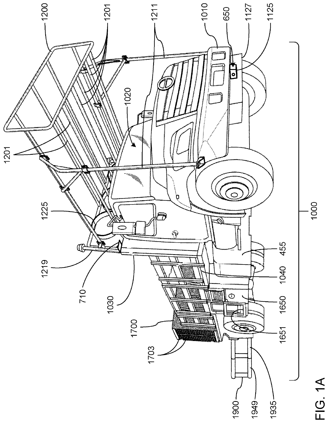
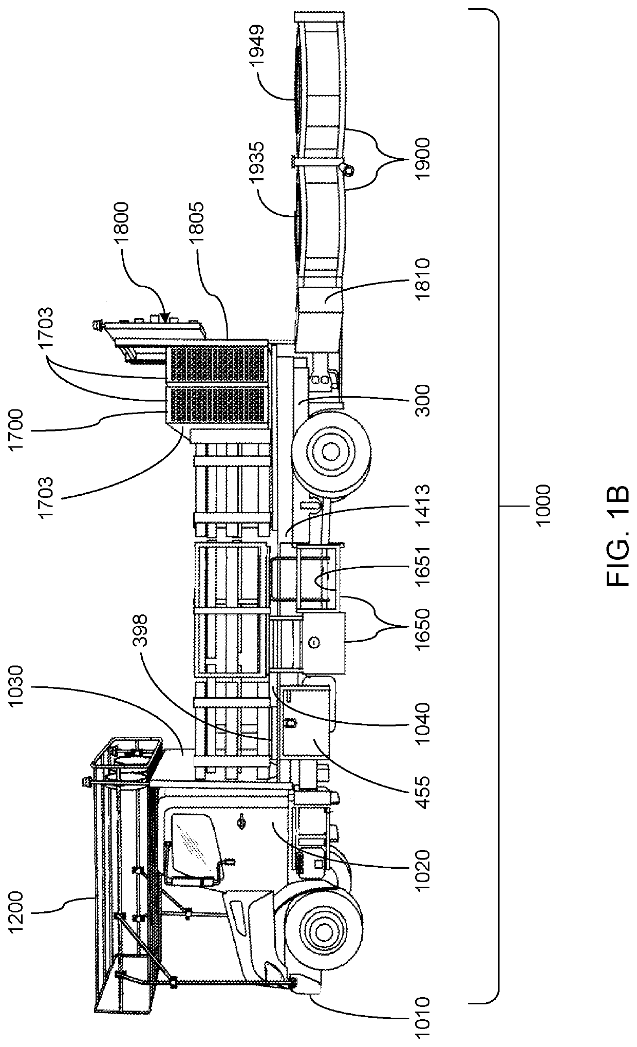
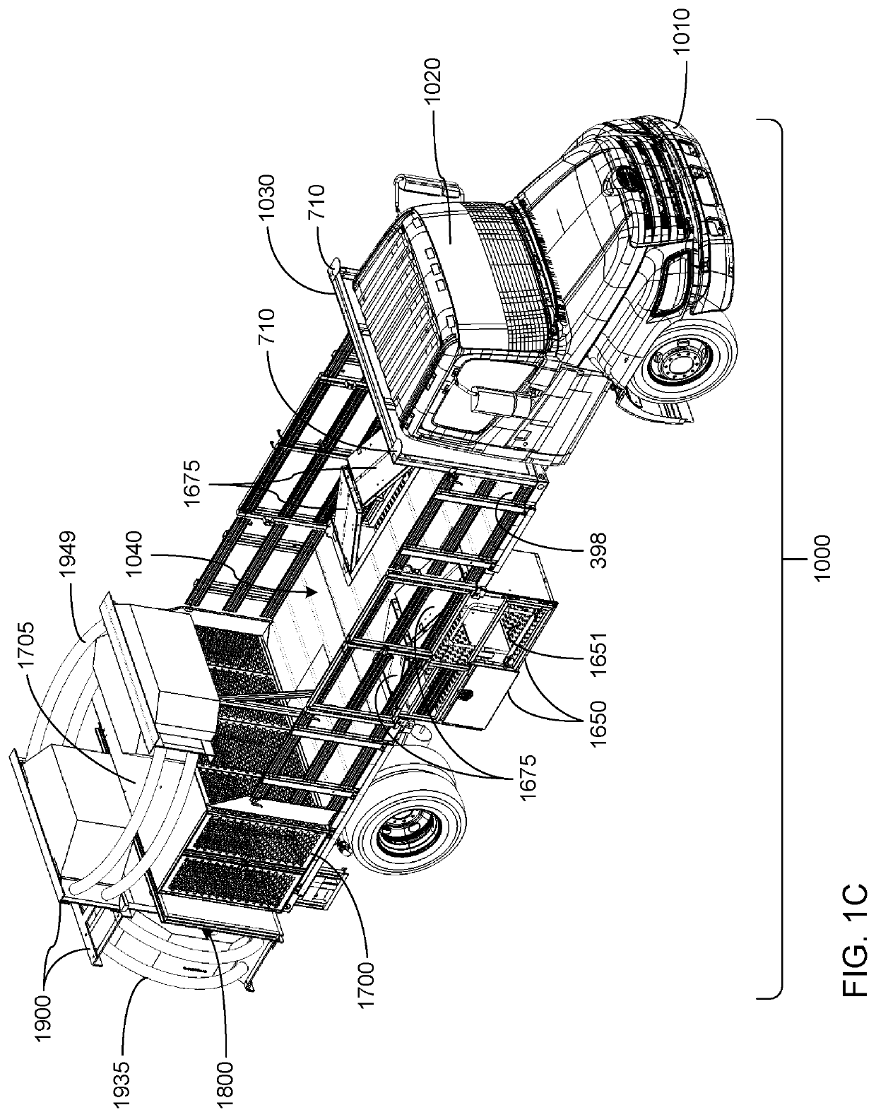
[0131]As can be seen in FIG. 3A, the pair of elongate, horizontally-extending channel members 300 that form a frame are provided to underlie the forwardly-facing cabs 1020 of the safety truck embodiments 1000. The elongate channel members 300 also extend rearwardly to underlie the flatbeds 1040 of the safety truck embodiments 1000.

[0132]Shown in FIG. 3B is a weight frame attachment 1400 that is positioned atop the elongate channel members 300 as is shown in FIG. 3C.

[0133]The weight frame attachment 1400 is comprised of a pair of side members 1413 that are i...


PUM


Abstract

Embodiments of safety trucks incorporate multiple connection points to which a variety of attachments, or combinations of attachments, can be releasably and interchangeably coupled to enable their use with increased effectiveness to safeguard roadway construction, maintenance and repair personnel as they perform tasks within or relatively near to roadway workzones and worksites. Also, methods of operation of the safety truck embodiments enhance their ability to guard and protect roadway construction, maintenance and repair personnel while they work within or relatively near to roadway workzone and worksite locations.

Description

REFERENCES TO RELATED APPLICATIONS[0001]This Utility Application is a continuation-in-part of U.S. patent application Ser. No. 16 / 427,242 filed May 30, 2019; which is a continuation-in-part of U.S. patent application Ser. No. 16 / 159,813 filed Oct. 15, 2018 (since issued Oct. 13, 2020 as U.S. Pat. No. 10,801,169); which is a continuation-in-part of U.S. patent application Ser. No. 16 / 132,376 filed Sep. 15, 2018 (since issued Feb. 11, 2020 as U.S. Pat. No. 10,556,545); which is a continuation-in-part of U.S. patent application Ser. No. 15 / 913,562 filed Mar. 6, 2018 (since issued Jun. 11, 2019 as U.S. Pat. No. 10,319,227); which is a continuation-in-part of U.S. patent application Ser. No. 15 / 197,685 filed Jun. 29, 2016 (since abandoned); the disclosure of each of which is incorporated herein by reference in its entirety for all purposes.[0002]U.S. patent application Ser. No. 16 / 427,242 also claims the benefit of the filing date of U.S. Provisional Application 62 / 780,909 filed Dec. 17,...

Claims


Application Information

Patent Timeline
Patent Type & Authority Applications(United States)
IPC IPC(8): E01F9/70B60R11/06B60R21/02B60P3/14B60R21/00
CPCE01F9/70B60R11/06B60R21/00B60P3/14B60R21/02E01F9/662E01F15/148B60R19/56B60R3/002B62D33/0207B62D33/0222
Inventor ROY, ROBERT HWASHBURN, ANDREW CPIGGOTT, JOSEPH TBALASUBRAMANIAN, SIDDHARTH
Owner ROYAL TRUCK & EQUIP INC
Why Eureka
Try Eureka