Furniture drive

a technology for furniture drives and drives, applied in the field of furniture drives, can solve the problems of affecting the kinematics affecting the actuation of the screw, and limited maximum mounting height of the furniture drive,

Active Publication Date: 2021-09-02
JULIUS BLUM GMBH
View PDF9 Cites 2 Cited by
  • Summary
  • Abstract
  • Description
  • Claims
  • Application Information

AI Technical Summary

Benefits of technology

[0007]It is an object of the present invention to propose a furniture drive of the type mentioned in the introductory part, thereby avoiding the above-discussed drawbacks.

Problems solved by technology

The connection between the sidewall and the top panel of the furniture carcass is usually established with the aid of screws, dowels and / or fins, whereby the maximum mounting height of the furniture drive is limited and the kinematics of the furniture drive can be negatively affected.
A drawback is the fact that the screw, in a mounted condition of the furniture drive, can only be accessed from the inside of the carrier, and that an actuation of the screw can be impeded by the components arranged within the interior of the carrier (pivoting arms, force storage member).

Method used


Image

  • Furniture drive
  • Furniture drive
  • Furniture drive

Examples


Embodiment Construction

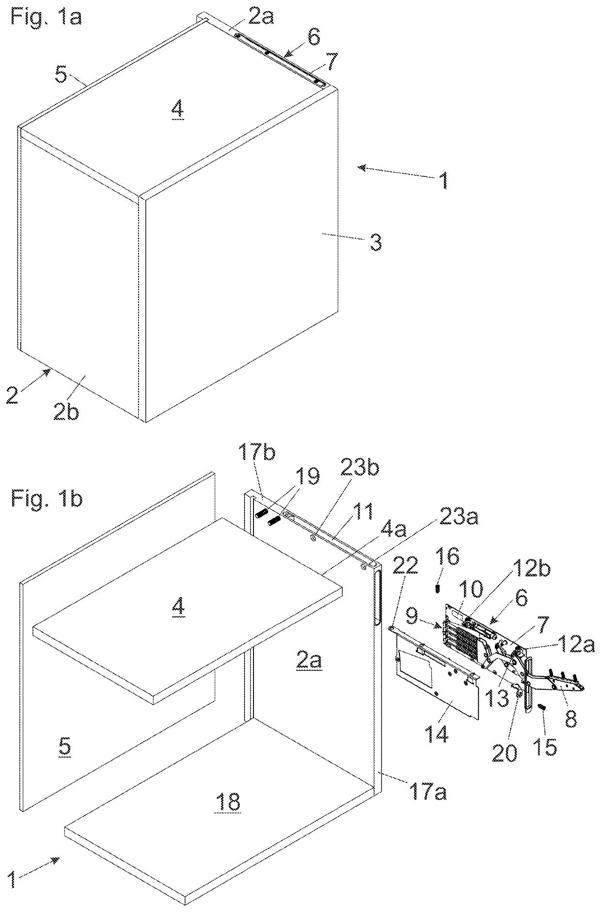
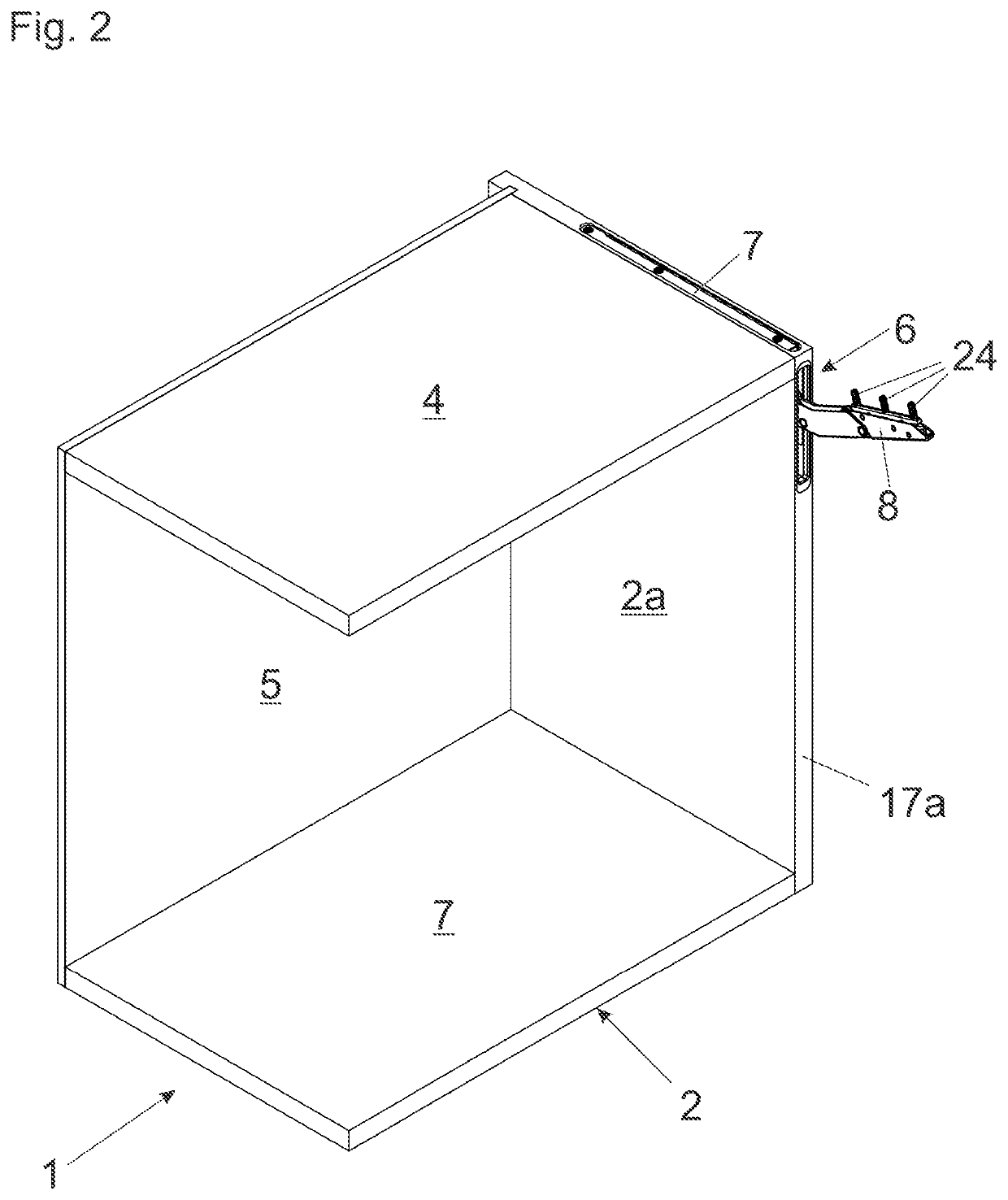
[0021]FIG. 1a shows a perspective view of an item of furniture 1 comprising a furniture carcass 2 and a movable furniture part 3. The movable furniture part 3 can be moved by a furniture drive 6 relative to the furniture carcass 2 between a vertical closed position and an elevated open position. The furniture carcass 2 includes two opposing sidewalls 2a, 2b, a furniture panel 4 in the form of a top panel extending horizontally in a mounted condition, and a rear wall 5. The furniture drive 6 includes a carrier 7 configured to be fixed to or within the sidewall 2a. In the shown embodiment, the carrier 7 is substantially entirely received within the sidewall 2a.

[0022]FIG. 1b shows the item of furniture 1 in an exploded view, in which the movable furniture part 3 and the sidewall 2b are not depicted for the sake of improved overview. The furniture carcass 2 includes the sidewalls 2a and 2b, a bottom panel 18, the horizontally aligned furniture panel 4 in the form of the top panel, and ...


PUM


Abstract

A furniture drive for moving a furniture part movably-supported relative to a furniture carcass includes a carrier configured to be fixed within or to a sidewall of the furniture carcass, and the carrier has a front face and a longitudinal side protruding substantially at a right angle from the front face. A pivotally supported actuating arm is provided for moving the movable furniture part, and fastening device can fasten a furniture panel of the furniture carcass. The furniture panel extends substantially horizontally in a mounted position, and a fastening device includes a movably-supported locking element for fastening the furniture panel. The locking element is configured to be accessible for a manual or for a tool-assisted actuation from a longitudinal side of the carrier, and the longitudinal side of the carrier faces towards the outside.

Description

BACKGROUND OF THE INVENTION[0001]The present invention relates to a furniture drive for moving a furniture part movably-supported relative to a furniture carcass. The furniture drive includes a carrier configured to be fixed within or to a sidewall of the furniture carcass, and the carrier has a front face and at least one longitudinal side protruding substantially at a right angle from the front face. A pivotally supported actuating arm is provided for moving the movable furniture part, and a fastening device is provided for fastening a furniture panel of the furniture carcass. The furniture panel extends substantially horizontally in a mounted position.[0002]Moreover, the invention relates to an item of furniture comprising a furniture carcass, a furniture part movably-supported relative to the furniture carcass, and at least one furniture drive of the type to be described for moving the movable furniture part.[0003]A furniture drive having a pivotally supported actuating arm for ...

Claims


Application Information

Patent Timeline
Patent Type & Authority Applications(United States)
IPC IPC(8): E05F1/10E05D3/12E05D15/40
CPCE05F1/1058E05D3/12E05Y2201/474E05Y2900/20E05Y2201/416E05D15/401E05F1/00F16B12/2036F16B12/2009E05Y2600/626E05Y2600/61E05Y2600/452E05D5/0276A47B96/20F16B12/24
Inventor HOLZAPFEL, ANDREASSCHLUGE, PHILIP
Owner JULIUS BLUM GMBH
Why Eureka
Try Eureka