Method for manufacturing glass panel unit

Pending Publication Date: 2021-09-02
PANASONIC INTELLECTUAL PROPERTY MANAGEMENT CO LTD
View PDF0 Cites 0 Cited by
  • Summary
  • Abstract
  • Description
  • Claims
  • Application Information

AI Technical Summary

Benefits of technology

[0007]The present disclosure reduces the chances

Problems solved by technology

This increases the chances of a residual gas being lef

Method used


Image

  • Method for manufacturing glass panel unit
  • Method for manufacturing glass panel unit
  • Method for manufacturing glass panel unit

Examples


Example

[0028]An exemplary embodiment of the present disclosure will now be described.

[0029]1. Embodiment

[0030]1.1. Overview

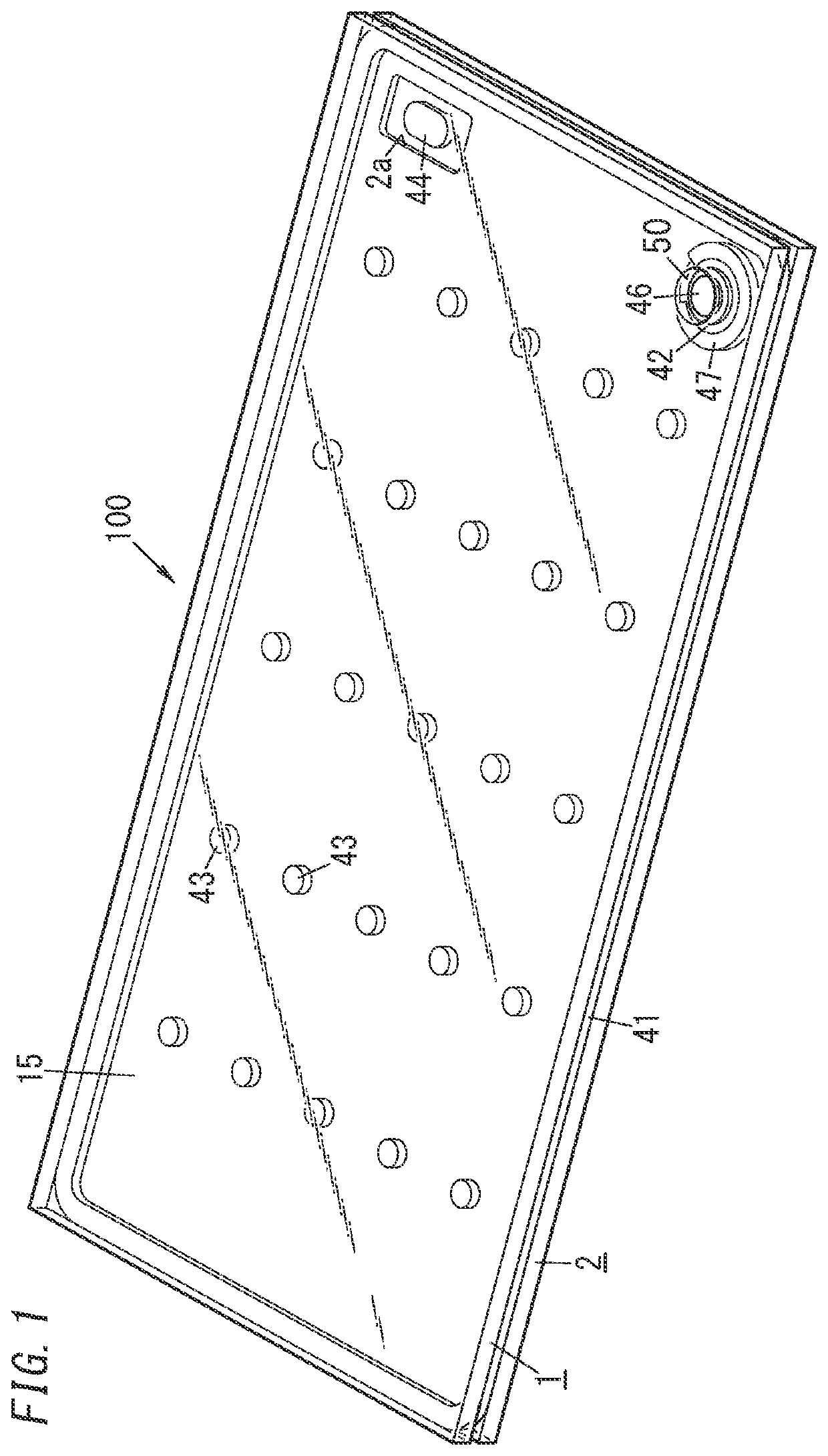
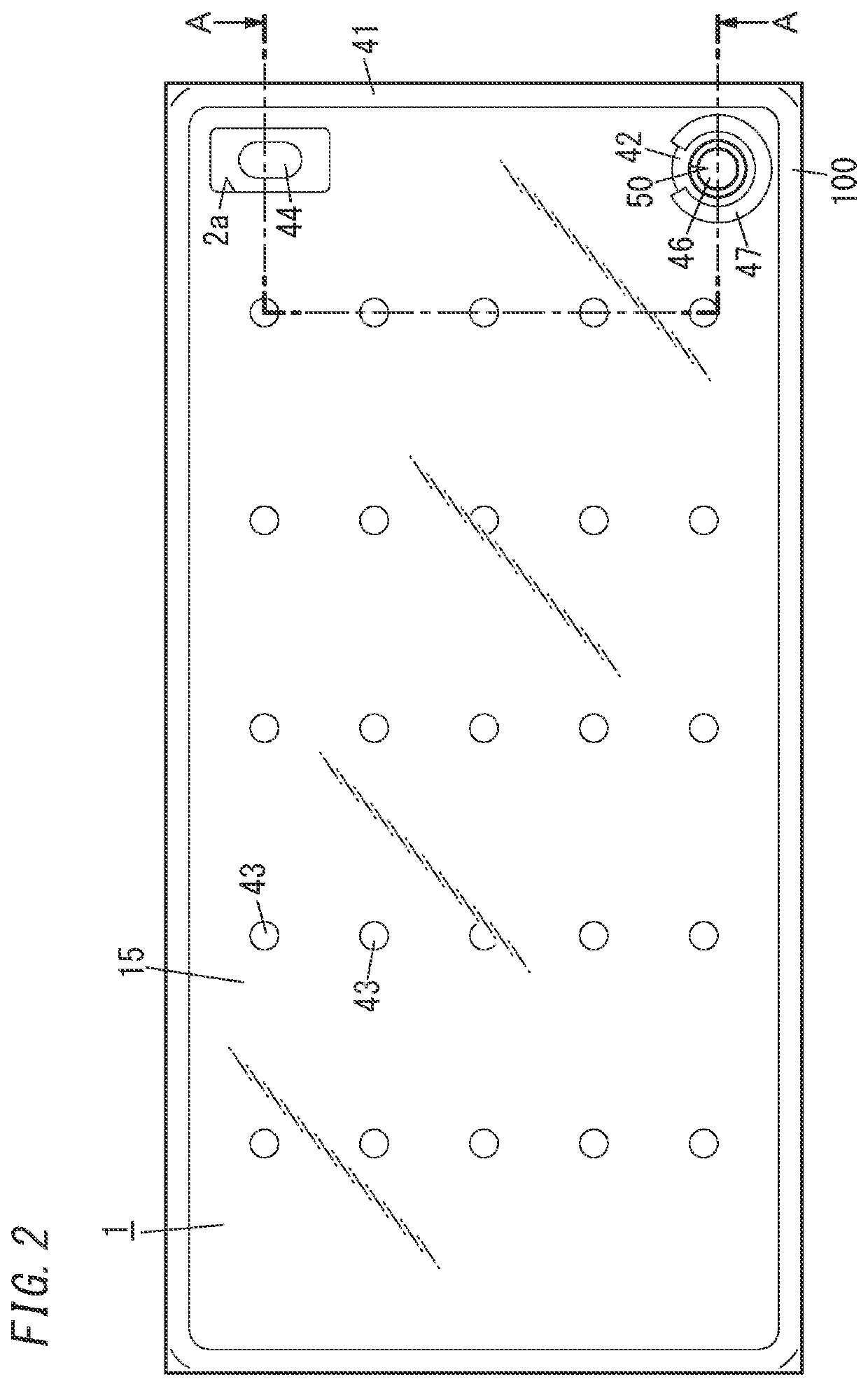
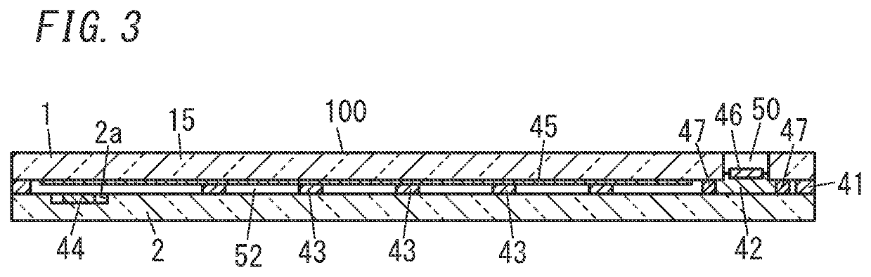
[0031]FIGS. 1-3 illustrate a glass panel unit (glass panel unit as a final product) 100 according to an exemplary embodiment. The glass panel unit 100 includes a first glass pane 1, a second glass pane 2, a frame member 41, a vacuum space 52, a port sealing material 42, an exhaust port 50, a dam member 47, a plurality of spacers (pillars) 43, and a gas adsorbent 44. The second glass pane 2 is arranged to face the first glass pane 1. The frame member 41 is provided between the first glass pane 1 and the second glass pane 2. The frame member 41 hermetically bonds the first glass pane 1 and the second glass pane 2 together. The vacuum space 52 is surrounded with the first glass pane 1, the second glass pane 2, and the frame member 41. The gas adsorbent 44 and the dam member 47 are located in the vacuum space 52. The port sealing material 42 is dammed up by the dam member ...


PUM

PropertyMeasurementUnit
Temperatureaaaaaaaaaa
Metallic bondaaaaaaaaaa
Thermal conductanceaaaaaaaaaa

Abstract

A method for manufacturing a glass panel unit includes an assembling step, a bonding step, a gas exhausting step, a sealing step, and an activating step. The bonding step includes melting a peripheral wall in a baking furnace at a first predetermined temperature to hermetically bond a first glass pane and a second glass pane together with the peripheral wall thus melted. The gas exhausting step includes exhausting a gas from an internal space through an exhaust port in the baking furnace to turn the internal space into a vacuum space. The sealing step includes locally heating to a temperature higher than a second predetermined temperature, and thereby melting, either a port sealing material or an exhaust pipe to seal the exhaust port and thereby obtain a work in progress. The activating step includes activating a gas adsorbent after the sealing step to obtain a glass panel unit.

Description

Technical Field[0001]The present disclosure generally relates to a method for manufacturing a glass panel unit, and more particularly relates to a method for manufacturing a glass panel unit suitably for use in windows, for example.BACKGROUND ART[0002]Patent Literature 1 discloses a method for manufacturing a vacuum-insulated multi-pane glazing. According to the manufacturing method of Patent Literature 1, low-melting glass in a paste form (first low-melting glass) is interposed between respective peripheral edge portions of a pair of glass panes (hereinafter referred to as a “first glass pane” and a “second glass pane,” respectively). Then, the first and second glass panes are bonded together by having the first low-melting glass melted in a baking furnace. Subsequently, a getter is introduced into a suction port of the first glass pane, and then a gas in the gap between the first and second glass panes (i.e., an internal space) is exhausted through the suction port with the intern...

Claims


Application Information

Patent Timeline
IPC IPC(8): E06B3/677C03C27/06E06B3/66E06B3/663E06B3/673
CPCE06B3/6775C03C27/06E06B3/6612E06B2003/66338E06B3/67334E06B3/66333E06B3/66357Y02A30/249Y02B80/22C03C27/08C03C27/10C03C17/06
Inventor ABEURIU, EIICHIHASEGAWA, KAZUYAISHIBASHI, TASUKUNONAKA, MASATAKASHIMIZU, TAKESHIISHIKAWA, HARUHIKO
Owner PANASONIC INTELLECTUAL PROPERTY MANAGEMENT CO LTD
Why Eureka
Try Eureka