Wireless power transfer holder

a technology of power transfer and wires, which is applied in the direction of electric/fluid circuit, transportation and packaging, passenger space, etc., can solve the problems of poor stability of the insertion of the electronic device, etc., and achieve excellent insertion stability and the effect of the electronic devi

Active Publication Date: 2021-09-02
TOYODA GOSEI CO LTD
View PDF0 Cites 2 Cited by
  • Summary
  • Abstract
  • Description
  • Claims
  • Application Information

AI Technical Summary

Benefits of technology

[0017]According to the present invention, it is possible to provide the wireless power transfer holder which is designed to be excellent in the insertability and the holding stability for the electronic device.

Problems solved by technology

Thus, there has been a problem with the stability of the posture of the held electronic device being poor.
In addition, when an upper and lower holding structure to be fitted with the electronic device has been employed to hold two right upper and lower portions and two left upper and lower portions in the opposite width directions, respectively, of the electronic device, there has been a problem with the insertability in the insertion of the electronic device becoming poor due to an increase in friction and the like.

Method used


Image

  • Wireless power transfer holder
  • Wireless power transfer holder
  • Wireless power transfer holder

Examples


first embodiment

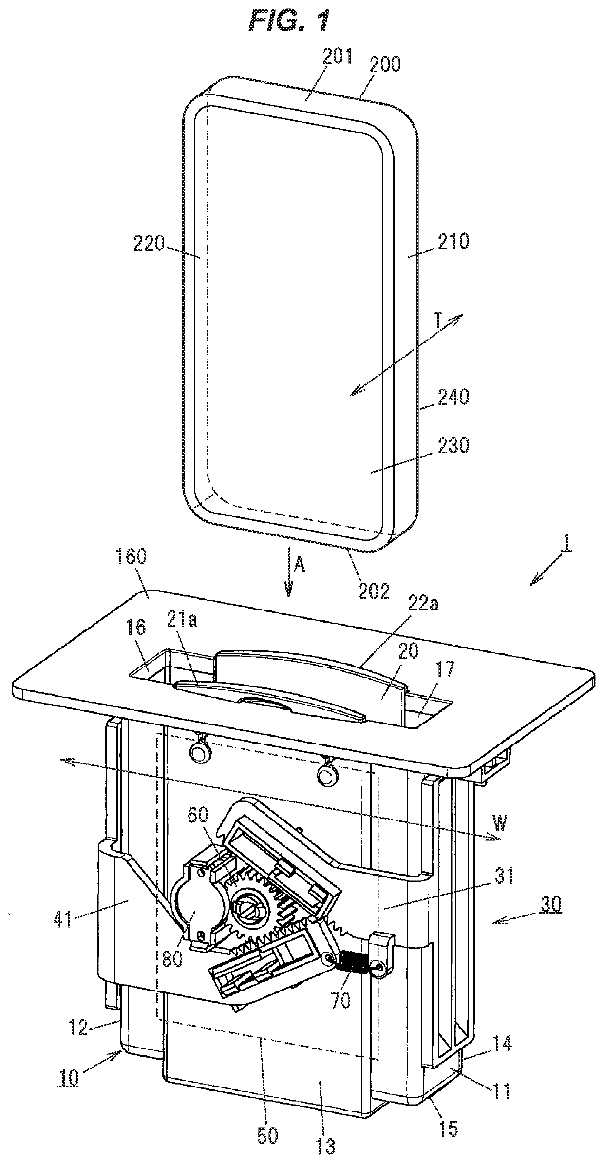
[0035]As shown in FIG. 1, a wireless power transfer holder 1 according to an embodiment of the present invention is being configured in such a manner as to include a holder case 10 including a receiving space 17, which is being formed by first opposite lateral walling portions 11 and 12, which are being configured to be provided opposite to opposite side surfaces 210 and 220, respectively, defining opposite width directions W of an electronic device 200, second opposite lateral walling portions 13 and 14, which are being configured to be provided opposite to a front surface 230 and a back surface 240, respectively, defining opposite thickness directions T of the electronic device 200, a bottom portion 15, which is closing one end of a spatial portion formed by the first opposite lateral walling portions 11 and 12 and the second opposite lateral walling portions 13 and 14, and an open portion 16, which is being formed opposite to the bottom portion 15, so that the electronic device 2...

second embodiment

[0096]As shown in FIGS. 9, 10A and 10B, a supporting mechanism 300 according to a second embodiment is being provided on a lateral walling portion 314 of a holder case 310 on which the inductive power transferring device 50 is not being mounted, and the lateral walling portion 314 of the holder case 310 includes four second open portions 350 therein, while the supporting mechanism 300 includes a first constituent supporting member 331 and a second constituent supporting member 341, which are being configured in such a manner as to exert bias forces on the opposite side surfaces 210 and 220, respectively, of the electronic device 200 through the four second open portions 350. As a result, the bias forces can be exerted in such a manner as to hold the electronic device 200 in a predetermined position substantially coincided with the central axis CL of the holder case 10 in the opposite width directions W of the electronic device 200 shown in FIG. 1.

[0097]As shown in FIG. 10B, a first ...


PUM


Abstract

A wireless power transfer holder composed of a receiving space formed by first walling portions to be provided opposite side surfaces, respectively, defining width directions of an electronic device, second walling portions to be provided opposite front and back surfaces, respectively, defining thickness directions of the electronic device, a bottom portion, and an open portion formed opposite the bottom portion, first and second supporting members movable symmetrically forward or backward in the width directions from the first walling portions, respectively, toward the electronic device, to exert bias forces on the side surfaces, respectively, of the electronic device, and an inductive power transferring device mounted on one of the second walling portions to inductively transfer an electric power in a non-contact manner to the electronic device held in the receiving space. The first and second supporting members are configured to be moved while having symmetrical tilts, respectively, toward the electronic device.

Description

CROSS-REFERENCE TO RELATED APPLICATIONS[0001]The present application is based on Japanese patent application No. 2020-031991 filed on Feb. 27, 2020, the entire contents of which are incorporated herein by reference.TECHNICAL FIELD[0002]The present invention relates to a wireless power transfer holder.BACKGROUND ART[0003]Various types of structures have been proposed that provide a structure for an interior of a vehicle to be fitted with a smartphone. A structure to be fitted with a smartphone is installed on a center cluster of the vehicle, and this structure to be fitted with a smartphone is composed of a box shaped body having an opening and a specified space on the center cluster, and a door for closing the opening of the box shaped body. The structure to be fitted with a smartphone is of a type that the smartphone is being fitted to an interior member by opening the door of the box shaped body, placing the smartphone into the box shaped body through the opening of the box shaped...

Claims


Application Information

Patent Timeline
Patent Type & Authority Applications(United States)
IPC IPC(8): H02J50/00H02J7/00H02J50/10B60R7/04B60R16/03
CPCH02J50/005H02J7/0044B60R16/03B60R7/04H02J50/10B60R2011/0075B60R11/0241
Inventor ICHIKAWA, YUHKI
Owner TOYODA GOSEI CO LTD
Why Eureka
Try Eureka