Novel electric crane

A crane and electric technology, which is applied in the field of new electric cranes, can solve the problems of large pulling force of lifting rope, broken lifting rope, and swinging of heavy objects back and forth, so as to avoid damage and ensure the effect of buffering.

Inactive Publication Date: 2018-11-16
HEFEI KIWI HEAVY MACHINERY CO LTD
View PDF0 Cites 0 Cited by
  • Summary
  • Abstract
  • Description
  • Claims
  • Application Information

AI Technical Summary

Problems solved by technology

The hook at the bottom of the existing crane is mainly used to lift the heavy object, which can easily cause the heavy object to swing back and forth, thereby generating a large pulling force on the lifting rope, which in turn causes the lifting rope to break, resulting in on-site work. safety of personnel

Method used


Image

  • Novel electric crane
  • Novel electric crane
  • Novel electric crane

Examples


Embodiment 1

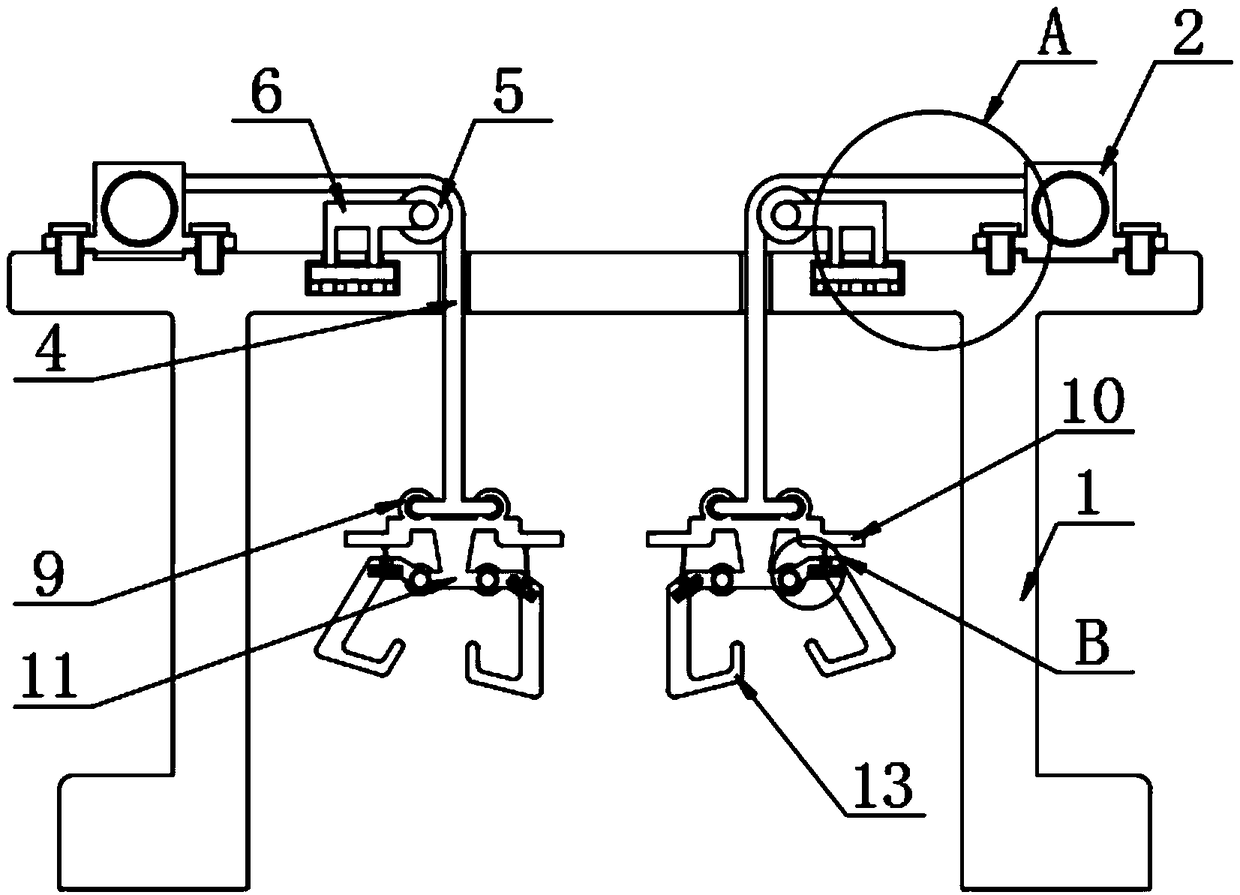
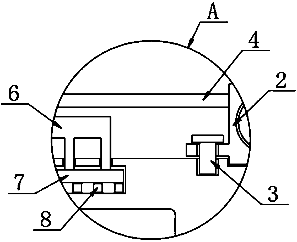
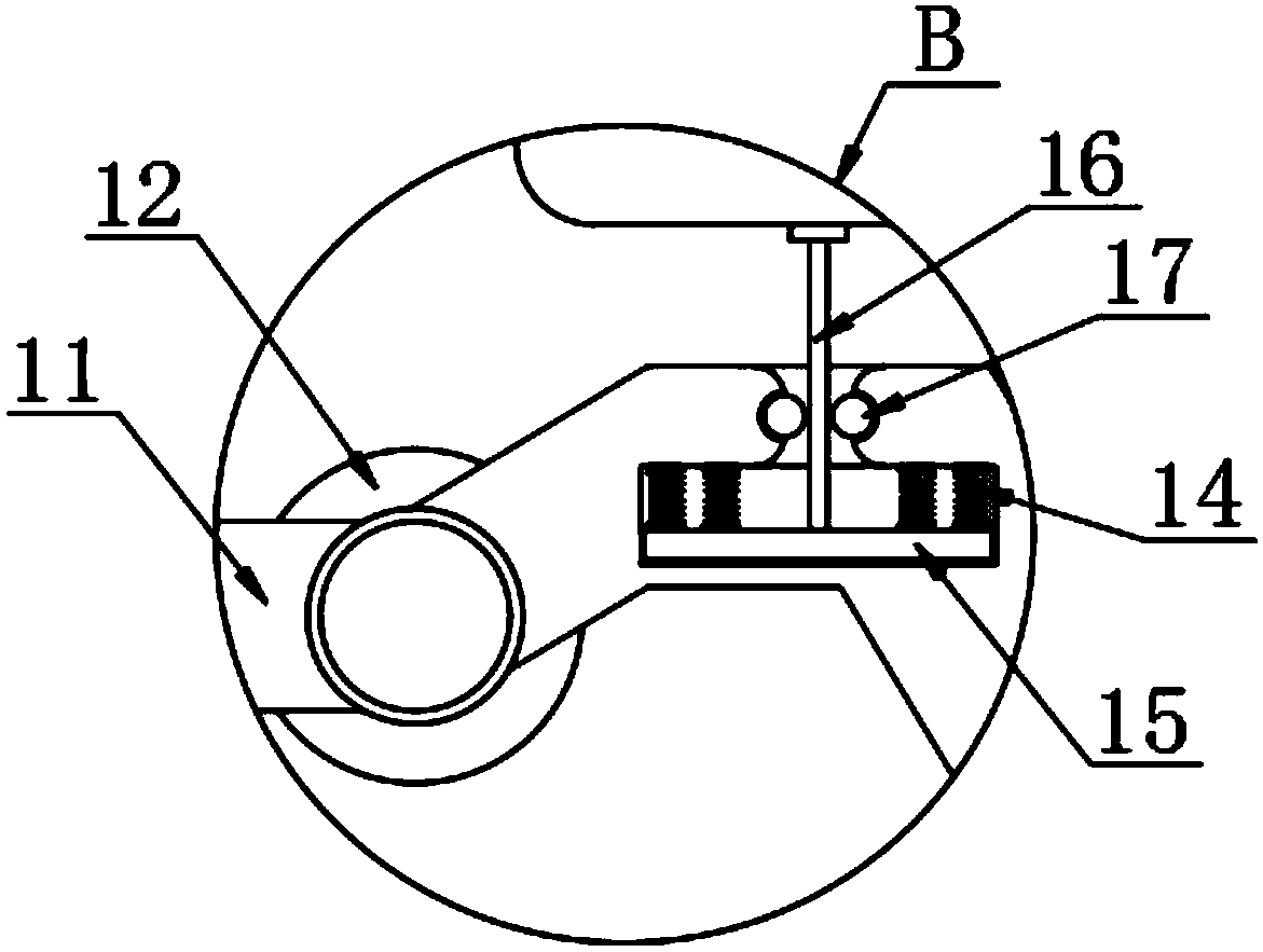
[0022] The present invention provides such Figure 1-3 A new type of electric crane shown includes a bracket 1, the top of the bracket 1 is provided with an electric winding roller 2, and both sides of the electric winding roller 2 are provided with fastening screws 3, and the electric winding roller 2 One side is provided with a hoisting rope 4, and the inside of the hoisting rope 4 is provided with a turning roller 5, and one side of the turning roller 5 is provided with a card frame 6, and the bottom of the card frame 6 is provided with a pressing plate 7, and the bottom of the pressing plate 7 is provided with a There is a rubber block 8, and one end of the lifting rope 4 is provided with a pull ring 9, and the bottom of the pull ring 9 is provided with a pull frame 10, and the bottom of the pull frame 10 is provided with a connecting frame 11, and both sides of the connecting frame 11 are provided with rotating shafts 12. A hook 13 is provided on one side of the rotating ...

Embodiment 2

[0025] The electric winding roller 2 is fixedly connected to the top surface of the support 1 through the fastening screw 3, and after the fastening screw 3 passes through the clamp, the electric winding roller 2 is fastened on the top of the support 1 to prevent the electric winding roller 2 from Shaking occurs during work, and one end of the hoisting rope 4 is connected to the electric winding roller 2, so that the hoisting rope 4 can be wound up or released by the electric winding roller 2.

[0026] The other end of the hoisting rope 4 is fixedly connected to the pull ring 9, which increases the stability of the binding and prevents the hoisting rope 4 from breaking away from the pull ring 9. The hoisting rope 4 is matched with the steering roller 5, which is convenient to change the lifting position through the steering roller 5. The running direction of the rope 4 can smoothly lift the heavy object.

[0027] The pull ring 9, the pull frame 10 and the connecting frame 11 a...


PUM


Abstract

The invention discloses a novel electric crane. The novel electric crane comprise supports, electric rollers are arranged at the top of the supports, fastening screws are arranged at two sides of theelectric rollers, a lifting rope is arranged at one side of the electric roller, a turning roller is arranged at an inner side of the lifting rope, a clamp rack is arranged at one side of the turningroller, a pressing plate is arranged at the bottom of the clamp rack, a rubber block is arranged at the bottom of the pressing plate, a draw ring is arranged at one end of the lifting rope, a draw rack is arranged at the bottom of the draw ring, a connection rack is arranged at the bottom of the draw rack, rotating shafts are arranged at two sides of the connection rack, and a hook is arranged atone side of the rotating shaft. The hook is arranged and is in an expansion state, a heavy object is buckled at the hook through the rope, the heavy object drives the hook to downwardly move, a connection rope drives the pressing plate to generate the pressing effect on the spring, the connection rope is rotated at the surface of a rotation rod, the hood rotates by taking a rotating shaft as an axle center, and two hooks increase the hanging stability of the heavy object.

Description

technical field [0001] The invention relates to the technical field of crane equipment, in particular to a novel electric crane. Background technique [0002] A crane refers to a multi-action hoisting machine that vertically lifts and horizontally transports heavy objects within a certain range, also known as a crane, aerial crane, crane, etc. The hook at the bottom of the existing crane is mainly used to lift the heavy object, which can easily cause the heavy object to swing back and forth, thereby generating a large pulling force on the lifting rope, which in turn causes the lifting rope to break, resulting in on-site work. safety of personnel. [0003] Therefore, it is necessary to invent a new type of electric crane to solve the above problems. Contents of the invention [0004] The object of the present invention is to provide a new type of electric crane. Since the hook is in the expanded state, it is convenient to hang the heavy object on the hook through the rope...

Claims


Application Information

Patent Timeline
Patent Type & Authority Applications(China)
IPC IPC(8): B66C25/00B66C13/04B66C1/34B66D1/12
CPCB66C25/00B66C1/34B66C13/04B66D1/12
Inventor 杨孝先龚子运王金龙黄浩
Owner HEFEI KIWI HEAVY MACHINERY CO LTD
Why Eureka
Try Eureka