A full-section shaft excavation method

A full-section, vertical shaft technology, applied in vertical shaft equipment, sinking, earthwork drilling and mining, etc., can solve the problems of narrow segment assembly space, low reliability of shaft excavation, shield body and segment rotation, etc., to improve reliability Improve performance and excavation efficiency, simplify the construction process and save space

Active Publication Date: 2022-07-08
SINOHYDRO JIAJIANG HYDRAULIC MACHINERY +1
View PDF5 Cites 0 Cited by
  • Summary
  • Abstract
  • Description
  • Claims
  • Application Information

AI Technical Summary

Problems solved by technology

[0005] The shaft boring machine disclosed in this patent document adopts walking-type tunneling to improve the working efficiency of the shaft boring machine. However, the space for segment assembly is narrow and the process is complicated. Low reliability, resulting in lower overall tunneling efficiency

Method used


Image

  • A full-section shaft excavation method
  • A full-section shaft excavation method

Examples


Embodiment 1

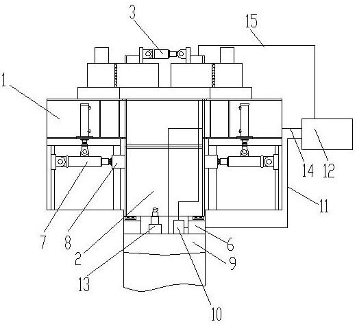
[0034] see figure 1 and figure 2 , a full-section shaft excavation method, comprising the following steps:

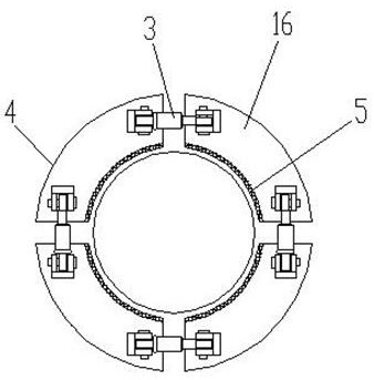
[0035] a. Wellhead excavation and foundation construction, install and fix the wellhead frame 1 of the full-section vertical shaft boring machine on the ground plane, hoist the arc-shaped steel pipe sheets by a crane, and assemble and connect a plurality of arc-shaped steel pipe sheets to form a ring-shaped steel pipe 2;

[0036] b. The holding device works, the oil cylinder 3 is retracted, the holding ring 4 is closed, and the holding ring 4 holds the ring 4-shaped steel pipe and the shield body 6 under the action of the friction force of the holding friction block 5; the guiding and propulsion device works , the pushing oil cylinder 7 pushes out the guide friction block 8, the guiding friction block 8 presses the outer wall of the annular steel pipe 2, the guiding friction block 8 transmits the thrust of the pushing oil cylinder 7 to the excavation cutter head 9, ho...

Embodiment 2

[0040] see figure 1 and figure 2 , a full-section shaft excavation method, comprising the following steps:

[0041] a. Wellhead excavation and foundation construction, install and fix the wellhead frame 1 of the full-section vertical shaft boring machine on the ground plane, hoist the arc-shaped steel pipe sheets by a crane, and assemble and connect a plurality of arc-shaped steel pipe sheets to form a ring-shaped steel pipe 2;

[0042] b. The holding device works, the oil cylinder 3 is retracted, the holding ring 4 is closed, and the holding ring 4 holds the ring 4-shaped steel pipe and the shield body 6 under the action of the friction force of the holding friction block 5; the guiding and propulsion device works , the pushing oil cylinder 7 pushes out the guide friction block 8, the guiding friction block 8 presses the outer wall of the annular steel pipe 2, the guiding friction block 8 transmits the thrust of the pushing oil cylinder 7 to the excavation cutter head 9, ho...

Embodiment 3

[0047] see figure 1 and figure 2 , a full-section shaft excavation method, comprising the following steps:

[0048] a. Wellhead excavation and foundation construction, install and fix the wellhead frame 1 of the full-section vertical shaft boring machine on the ground plane, hoist the arc-shaped steel pipe sheets by a crane, and assemble and connect a plurality of arc-shaped steel pipe sheets to form a ring-shaped steel pipe 2;

[0049] b. The holding device works, the oil cylinder 3 is retracted, the holding ring 4 is closed, and the holding ring 4 holds the ring 4-shaped steel pipe and the shield body 6 under the action of the friction force of the holding friction block 5; the guiding and propulsion device works , the pushing oil cylinder 7 pushes out the guide friction block 8, the guiding friction block 8 presses the outer wall of the annular steel pipe 2, the guiding friction block 8 transmits the thrust of the pushing oil cylinder 7 to the excavation cutter head 9, ho...


PUM


Abstract

The invention discloses a full-section shaft excavation method, belonging to the technical field of shaft construction. Hold the annular steel pipe and the shield body; the guiding friction block transmits the thrust of the propulsion cylinder to the excavation cutter head, and the excavation cutter head rotates downward and vertically under the action of the driving member, and the mud-water circulation device works to discharge the mud; c. The crane lifts the arc-shaped steel pipe sheet, assembles the next ring-shaped steel pipe, and connects the two ring-shaped steel pipes, holds the oil cylinder to extend, opens the holding ring, and repeats the excavation operation. The invention can save space for the assembly of the arc-shaped steel pipe sheet, improve the holding reliability, simplify the construction process, facilitate disassembly and assembly, and can quickly discharge the mud during the downward vertical excavation process, and improve the reliability and excavation efficiency of the vertical shaft excavation. , the whole excavation process is easy to operate.

Description

technical field [0001] The invention relates to the technical field of shaft construction, in particular to a full-section shaft excavation method. Background technique [0002] A well-shaped pipe with an upright wall is called a shaft, and the shaft is actually a collapse funnel. Shafts are square, elongated or irregularly circular in plan profile. The elongated shape develops along one set of joints, and the square or round shape develops along two sets of joints. The walls of the well are steep and almost upright. Shafts are widely used in water conservancy and hydropower projects for water intake, water diversion, ventilation and exhaust, slag slippage and air supply. Shaft construction has the characteristics of small footprint and less interference to surrounding construction. However, due to the small construction space, long construction period, many climbing and edge operations, and inconvenient traffic, the safety risks of vertical shaft construction are promine...

Claims


Application Information

Patent Timeline
Patent Type & Authority Patents(China)
IPC IPC(8): E21D1/08E21D1/06E21D5/10E21D5/12E21D7/00E21B21/00
CPCE21D1/08E21D1/06E21D5/10E21D5/12E21D7/00E21B21/00Y02E10/20
Inventor 曾文李欣欣吴思够张君松代新启许强谭晓波
Owner SINOHYDRO JIAJIANG HYDRAULIC MACHINERY
Why Eureka
Try Eureka