Cooling device
a cooling device and cooling fan technology, applied in the direction of cooling/ventilation/heating modification, basic electric elements, electrical equipment, etc., can solve the problem that the cooling air cannot be efficiently blown to the radiator, and achieve the effect of improving the cooling efficiency of the radiator
- Summary
- Abstract
- Description
- Claims
- Application Information
AI Technical Summary
Benefits of technology
Problems solved by technology
Method used
Image
Examples
first embodiment
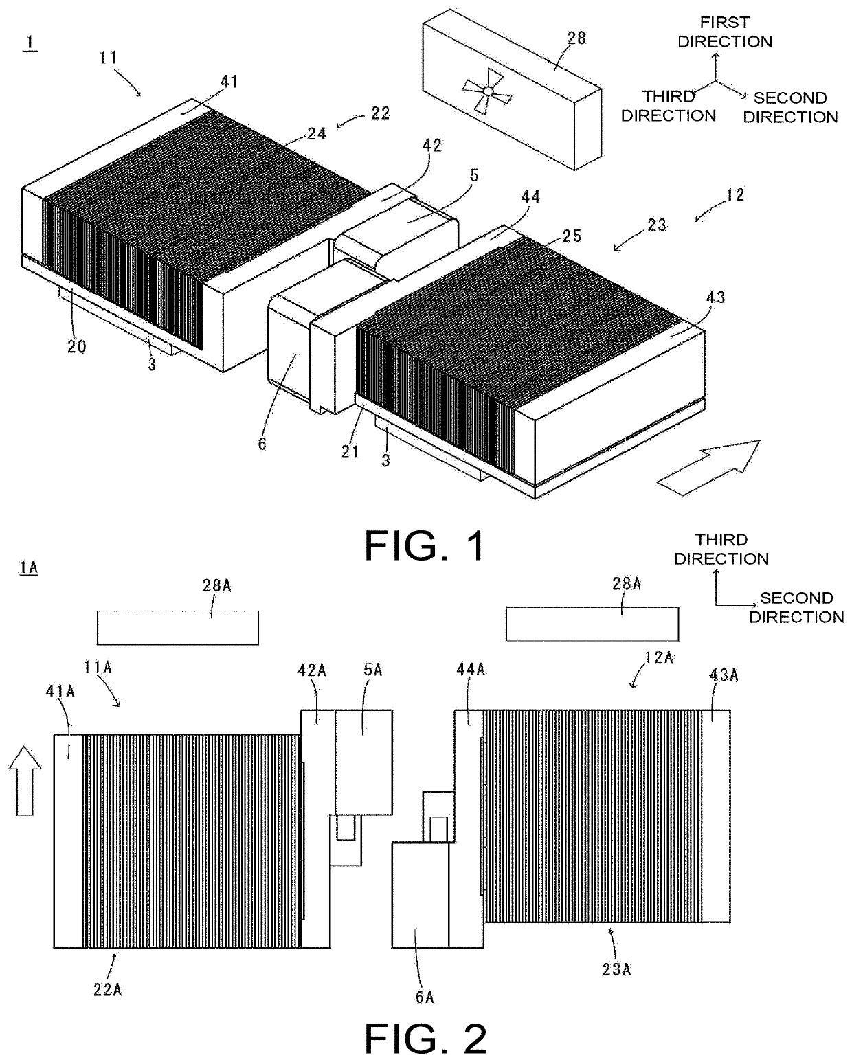
[0017]A cooling device 1 according to an exemplary embodiment of the disclosure will be described. FIG. 1 is a perspective view of a cooling device according to a first exemplary embodiment of the disclosure.
[0018]The cooling device 1 has at least two cooling units. In the present application, one of the two cooling units will be described as a first cooling unit 11 and the other as a second cooling unit 12. In addition, descriptions of the second cooling unit 12 will be made only with respect to differences from the first cooling unit 11. For the sake of convenience, when the second cooling unit 12 is described, portions having the same configurations as those of the first cooling unit 11 are denoted by the same reference signs as those of the first cooling unit 11.
[0019]The cooling units 11 and 12 have cold plates 20 and 21, radiators 22 and 23, and pumps 5 and 6. The radiators 22 and 23 are disposed on the cold plates 20 and 21. Upper surfaces of the cold plates 20 and 21 are in ...
second embodiment
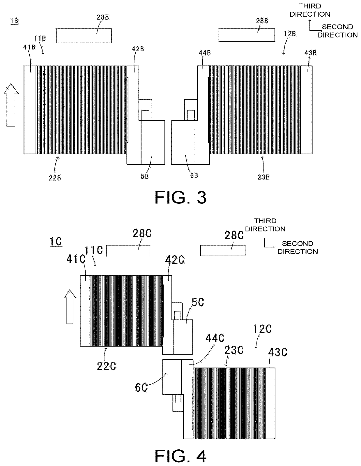
[0062]A cooling device 1A according to a second exemplary embodiment of the disclosure will be described. FIG. 2 is a plan view of the cooling device 1A according to the second exemplary embodiment. For the sake of convenience of explanation, portions the same as those in the first embodiment are denoted by the same reference signs.
[0063]In the present embodiment, a pump 5A of a first cooling unit 11A and a second cooling unit 12A are disposed adjacent to each other. The pump 5A of the first cooling unit 11A is disposed on a downstream side of the cooling air in the third direction front a pump 6A of the second cooling unit 12A. A second tank 42A of the first cooling unit 11A and the pump 6A of the second cooling unit 12A face each other in the second direction, and a second tank 44A of the second cooling unit 12A and the pump 5A of the first cooling unit 11A face each other in the second direction.
[0064]In the present embodiment, one end portion of the pump 5A of the first cooling ...
third embodiment
[0066]A cooling device 1B according to a third exemplary embodiment of the disclosure will be described. FIG. 3 is a plan view of the cooling device 1B according to the third exemplary embodiment. For convenience of explanation, portions the same as those in the first embodiment are denoted by the same reference signs.
[0067]In the present embodiment, the pump 5B of the first cooling unit 11B and the second cooling unit 12B are disposed adjacent to each other. The pump 5B of the first cooling unit 11B and the pump 6B of the second cooling unit 12B are disposed to face each other in the second direction.
[0068]Specifically, one surface of the pump 5B in the second direction and the other surface of the pump 6B in the second direction are disposed to face each other in the second direction. By disposing the pump 5B and the pump 6B to face each other in the second direction and reducing the gap between the pump 5B and the pump 6B in the second direction, the cooling air flowing in from t...
PUM
 Abstract
Description
Claims
Application Information
 - R&D
- Intellectual Property
- Life Sciences
- Materials
- Tech Scout
- Unparalleled Data Quality
- Higher Quality Content
- 60% Fewer Hallucinations
Browse by: Latest US Patents, China's latest patents, Technical Efficacy Thesaurus, Application Domain, Technology Topic, Popular Technical Reports.
© 2025 PatSnap. All rights reserved.Legal|Privacy policy|Modern Slavery Act Transparency Statement|Sitemap|About US| Contact US: help@patsnap.com


