
Air jet emission method used in liquid ejecting apparatus, and the apparatus

a liquid ejecting apparatus and air jet technology, applied in the direction of printing, other printing apparatus, etc., can solve the problems of poor print quality, displacement of ink droplets ejecting in the landing position, and the resultant running of ink droplets

Active Publication Date: 2017-02-21
SEIKO EPSON CORP
View PDF2 Cites 0 Cited by
  • Summary
  • Abstract
  • Description
  • Claims
  • Application Information

AI Technical Summary

Benefits of technology

The invention provides an air jet emission method and liquid ejecting apparatus that can effectively blow dust off a medium before printing. The air or gas is blown to the medium at a predetermined area using a blower with an elongated nozzle opening and evenly applies the jet of air or gas to the medium's area. The air inlet of the blower is located above the nozzle opening to reduce the possibility of taking in dust. This method and apparatus improve print quality and prevent dust settlement on the nozzle surface.

Problems solved by technology

If printing is performed on such a medium the surface of which is contaminated with dust, it causes displacement in the landing positions of ink droplets ejected, resulting in poor print quality.
However, in JP-A-2003-220695, there is a possibility that the air stream produced at the upstream side as viewed from the recording head will cause displacement in the landing positions of ink droplets ejected.
Moreover, when the charged dust is attracted onto the medium, depending on the attitude of the dust such as fiber particles, etc., there is a risk of the re-settlement of the dust into the nozzles of the recording head and the resultant running of ink droplets down onto the medium via the fiber particles.
In both of these cases, print quality will be poor.
The same problems could also arise in various kinds of liquid ejecting apparatuses.
Therefore, the medium in such a charge-released state has weakened attraction for dust.
Therefore, this preferred structure further reduces the possibility of taking in dust drifting in air.

Method used


Image

  • Air jet emission method used in liquid ejecting apparatus, and the apparatus
  • Air jet emission method used in liquid ejecting apparatus, and the apparatus
  • Air jet emission method used in liquid ejecting apparatus, and the apparatus

Examples


Embodiment Construction

[0026]With reference to the accompanying drawings, an exemplary embodiment of the present invention will now be explained.

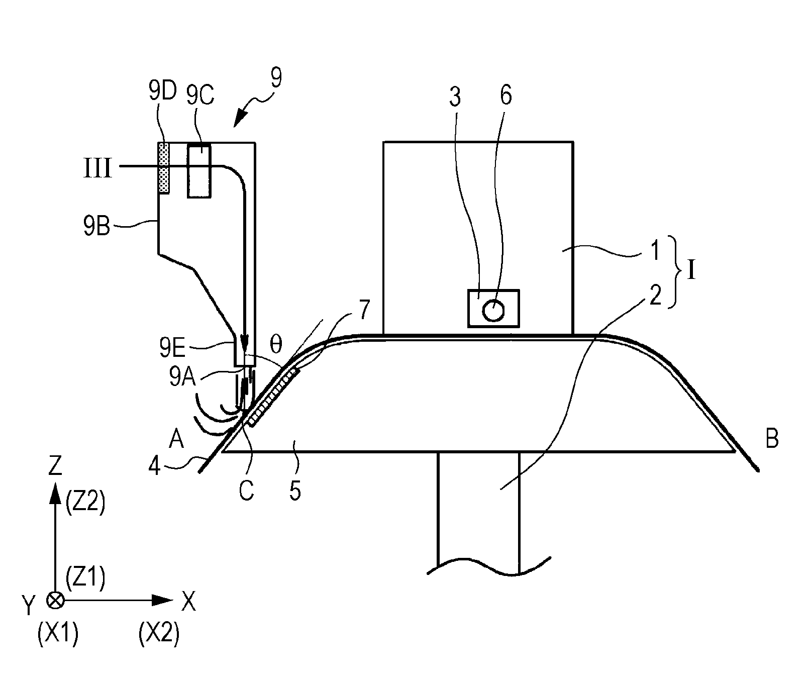
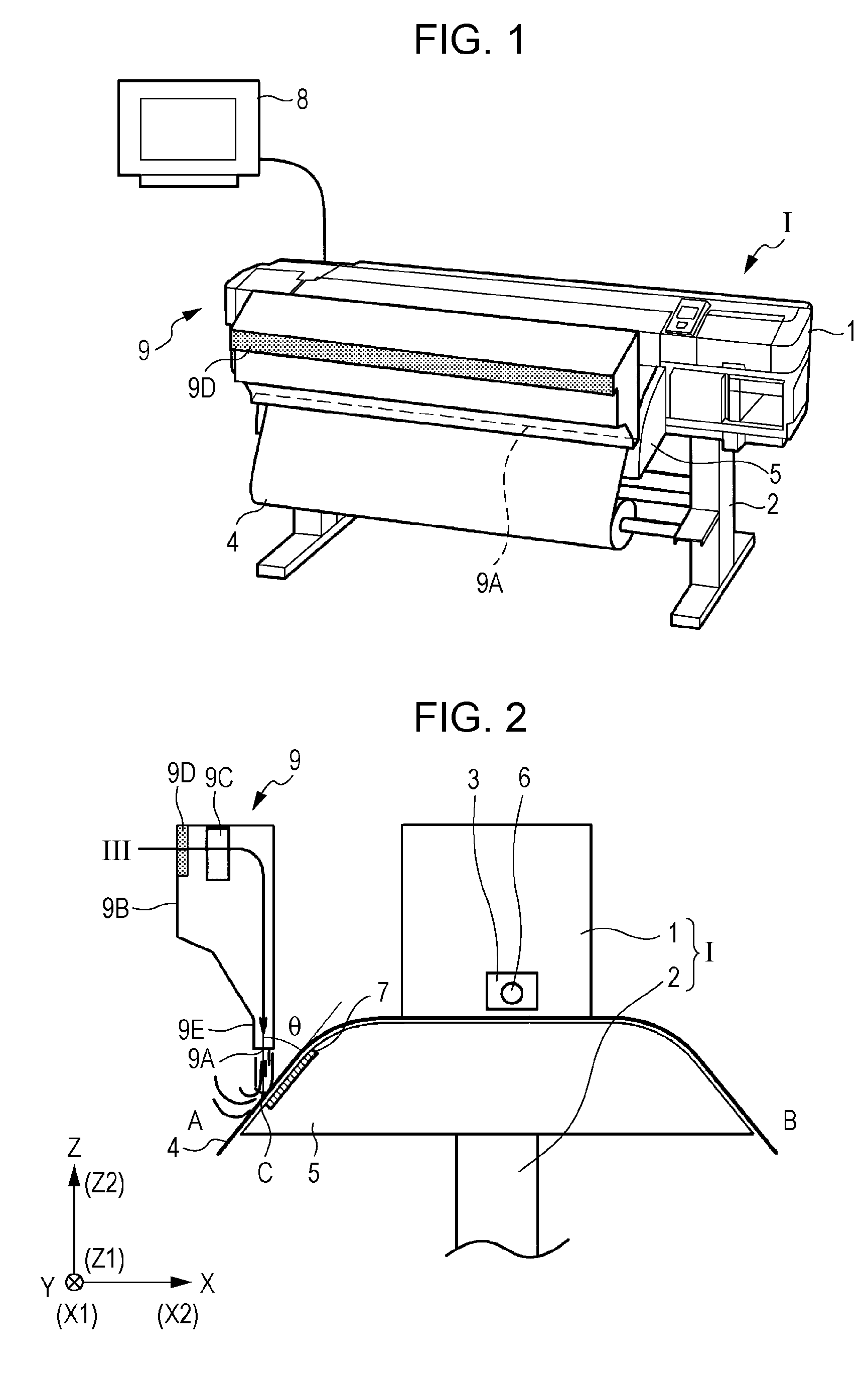
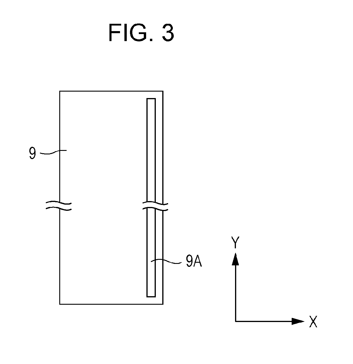
[0027]FIG. 1 is a schematic view of the overall structure of an ink-jet recording apparatus according to an exemplary embodiment of the invention. FIG. 2 is a partial enlarged side view showing an essential part of the ink-jet recording apparatus in cross section laterally. An ink-jet recording apparatus according to the present embodiment (hereinafter may be simply referred to as “recording apparatus”) I is a large format printer that has the structure illustrated in FIGS. 1 and 2. An ink-jet recording head (hereinafter may be simply referred to as “recording head”) 3 is built in the body 1 of the recording apparatus I (apparatus body). The apparatus body 1 is mounted on a stand 2. A medium 4, which is in the form of a roll, is supported by the stand 2. The recording apparatus I includes the medium 4, which is supported in the form of a roll by the stand 2 as me...


PUM


Abstract

Provided is an air jet emission method used in a recording apparatus. The recording apparatus performs predetermined printing by ejecting ink droplets from a recording head provided in an apparatus body onto a medium. The medium is fed into the apparatus body while being guided by a guide and is transported from an upstream side, which is one side with respect to the apparatus body, toward a downstream side, which is an opposite side with respect to the apparatus body. The air jet emission method comprises: emitting a jet of air onto a surface of the transported medium at a predetermined area over a heating device at the upstream side, thereby blowing dust off the surface of the transported medium. The heating device is provided in the guide so as to apply heat to the transported medium.

Description

[0001]The entire disclosure of Japanese Patent Application No: 2015-077972, filed Apr. 6, 2015 is expressly incorporated by reference herein in its entirety.BACKGROUND[0002]1. Technical Field[0003]The present invention relates to a method for emitting a jet of air in a liquid ejecting apparatus, and the apparatus. More particularly, the invention relates to an air jet emission technique that is useful when applied to a large format printer.[0004]2. Related Art[0005]A liquid ejecting apparatus is provided with a liquid ejecting head and performs predetermined printing by emitting liquid droplets from the liquid ejecting head onto a medium such as paper, cloth, a film, or the like. A typical example of such a liquid ejecting apparatus is an ink-jet recording apparatus (hereinafter may be simply referred to as “recording apparatus”), which is provided with an ink-jet recording head (hereinafter may be simply referred to as “recording head”) for ejecting ink droplets. A so-called large ...

Claims


Application Information

Patent Timeline
Patent Type & Authority Patents(United States)
IPC IPC(8): B41J29/17B41J11/00B41J2/165
CPCB41J29/17B41J11/002B41J2002/16555B41J29/377B41J11/0024B41J11/00244
Inventor SUZUKI, SHIGEKIYAMAZAKI, TOSHINOBUSATO, MASAHIKO
Owner SEIKO EPSON CORP
Learn More