
Electric fan

a technology of electric fans and fans, applied in the direction of liquid fuel engines, lighting and heating apparatus, heating types, etc., can solve the problems of continuously unpleasant sound and no longer feeling cool air, and achieve the effect of efficiently blowing cool wind

Inactive Publication Date: 2018-05-31
EARTH BLOW JAPAN INC
View PDF8 Cites 0 Cited by
  • Summary
  • Abstract
  • Description
  • Claims
  • Application Information

AI Technical Summary

Benefits of technology

The present invention is about an electric fan that can efficiently blow cool wind even if it has a large blade diameter and high flow rate. This means that the fan can provide effective cooling even at a high speed.

Problems solved by technology

However, since the electric fan basically does not have a function of decreasing the temperature of air, when the temperature of the air is too high, the person no longer feels that the air is cool.
In this kind of the cool wind fan, the water supplied beyond the water-retaining capacity of the evaporation filter falls from the evaporation filter into a tank, which results in making unpleasant sound continuously.

Method used


Image

  • Electric fan
  • Electric fan
  • Electric fan

Examples


Embodiment Construction

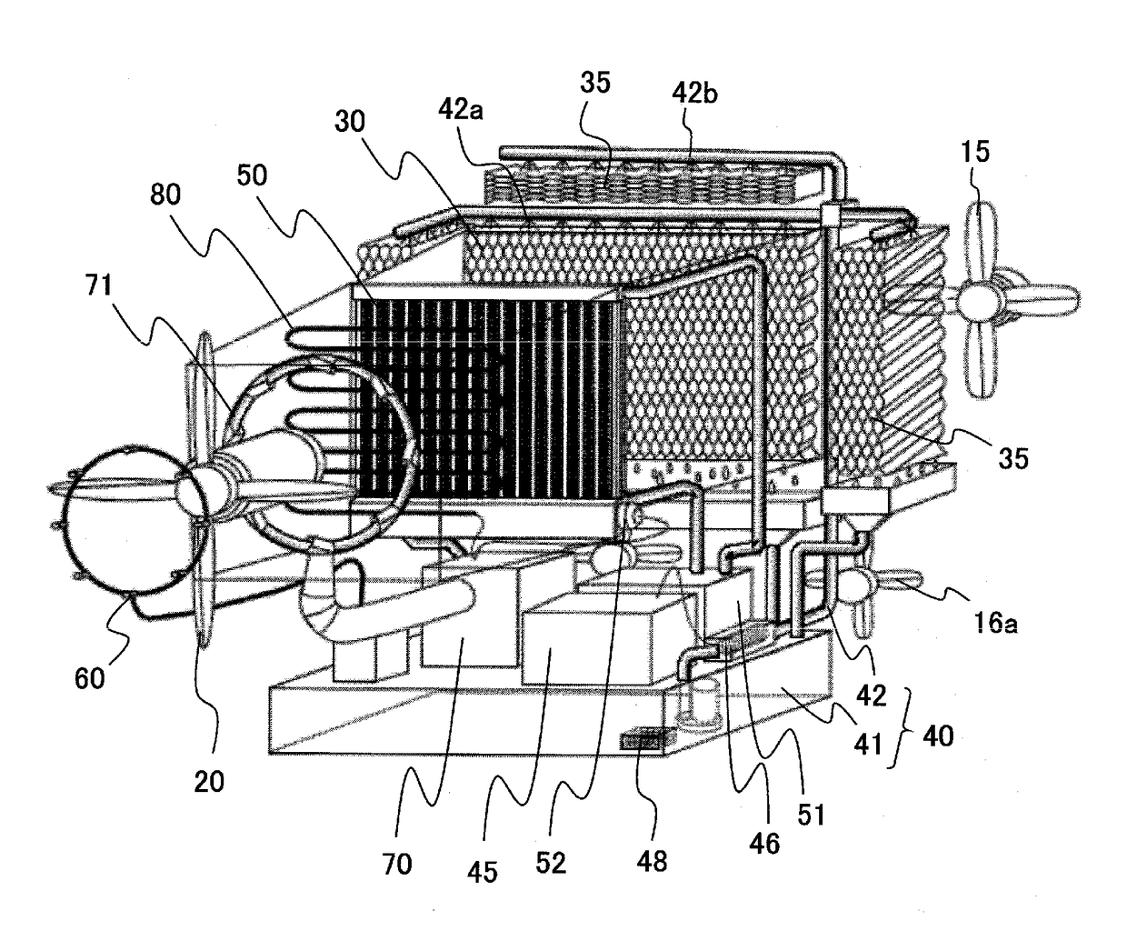
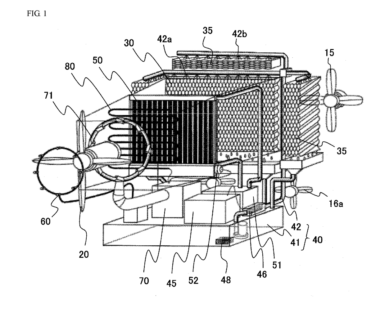
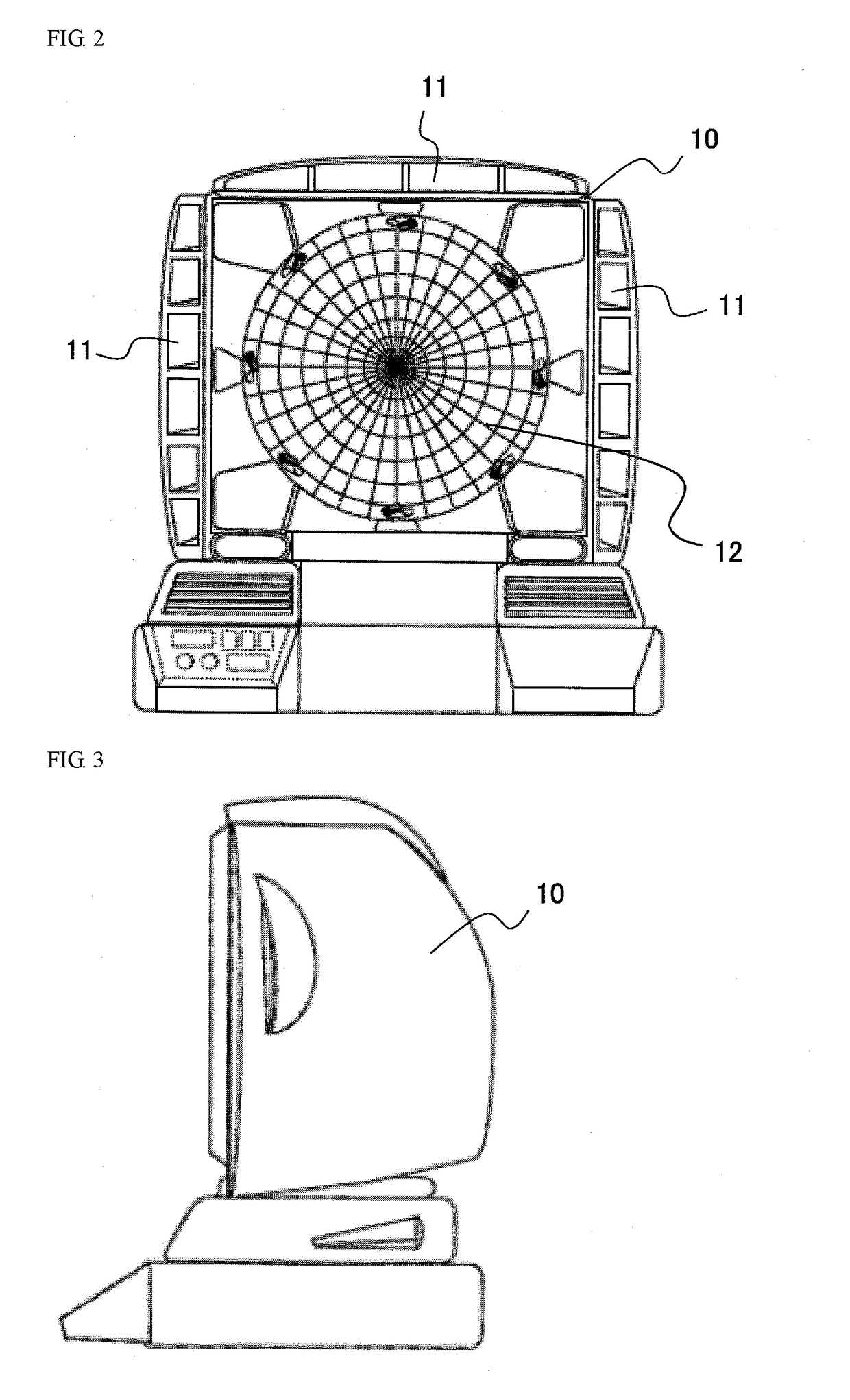
[0024]The electric fan of the present invention is an electric fan blowing cool wind by utilizing the vaporization heat of water contained in an evaporation filter. The electric fan of the present invention can blow cool wind efficiently even if the electric fan is a large flow rate fan having a large blade diameter. The inner structure of the electric fan according to one embodiment of the present invention is shown in FIG. 1, and the appearance of the electric fan according to one embodiment of the present invention is shown in FIGS. 2 to 4. In this electric fan, a suction port 11 for air and a blowing port 12 for air are formed on the front part of a housing 10, and an axial flow fan 20 is mounted inside the housing 10.

[0025]The housing 10 may be made from a plastic or may be made from a fiber-reinforced plastic (FRP). At least the inner surface of the housing 10 is preferably made from a heat insulating material such as a plastic foam in terms of the prevention of the temperatur...


PUM


Abstract

The present invention provides an electric fan capable of blowing cool wind efficiently even if the electric fan is a large flow rate fan having a large blade diameter. The electric fan of the present invention comprises: a housing having a suction port for air and a blowing port for air; an axial flow fan for suctioning air from the suction port into the housing and for blowing the suctioned air from the blowing port; an evaporation filter for passing the air suctioned from the suction port; a water supplying system capable of supplying water to the evaporation filter; an indirect heat exchanger for cooling the air passed through the evaporation filter, the indirect heat exchanger being disposed downstream from the evaporation filter; and a cooler for cooling a coolant for the indirect heat exchanger; wherein the suction port and the blowing port are formed on the same side surface of the housing; and wherein the blowing port is formed on the central part of the side surface of the housing, and the suction port is formed on the outer edge part of the blowing port.

Description

FIELD OF THE INVENTION[0001]The present invention relates to an electric fan for blowing cool wind by utilizing vaporization heat of water contained in an evaporation filter.BACKGROUND ART[0002]Although electric fans simply create a flow of air, the created flow of air blows off air heated on a surface of a person's human body, and thereby the person feels that the air from the electric fan is cool. However, since the electric fan basically does not have a function of decreasing the temperature of air, when the temperature of the air is too high, the person no longer feels that the air is cool.[0003]Therefore, an electric fan blowing cool wind by utilizing the vaporization heat of water to actively decrease the temperature of air, which is referred to as a cool wind fan, is used. More specifically, an evaporation filter is disposed in a path of air, and water is supplied to the evaporation filter. When the air passes through the evaporation filter containing water, the water contain...

Claims


Application Information

Patent Timeline
Patent Type & Authority Applications(United States)
IPC IPC(8): F04D25/08F24F1/00F24F6/04F04D29/58F04D29/70F24F1/0035F24F6/14
CPCF04D25/08F04D29/58F04D29/70F24F1/00F24F6/04F24F6/14F04D19/002F04D29/541F04D29/5826F24F1/0007F24F1/0035Y02B30/54
Inventor AIZAKI, TETSUYA
Owner EARTH BLOW JAPAN INC
Learn More