The present invention has been made in view of the circumstances as described above, and an object of the invention is to provide a jetting apparatus for a mixed flow of gas and liquid which has less blowing variations, can generate efficient blowing, and is convenient for use, by making blowing action of the mixed flow of the gas and the liquid uniform.
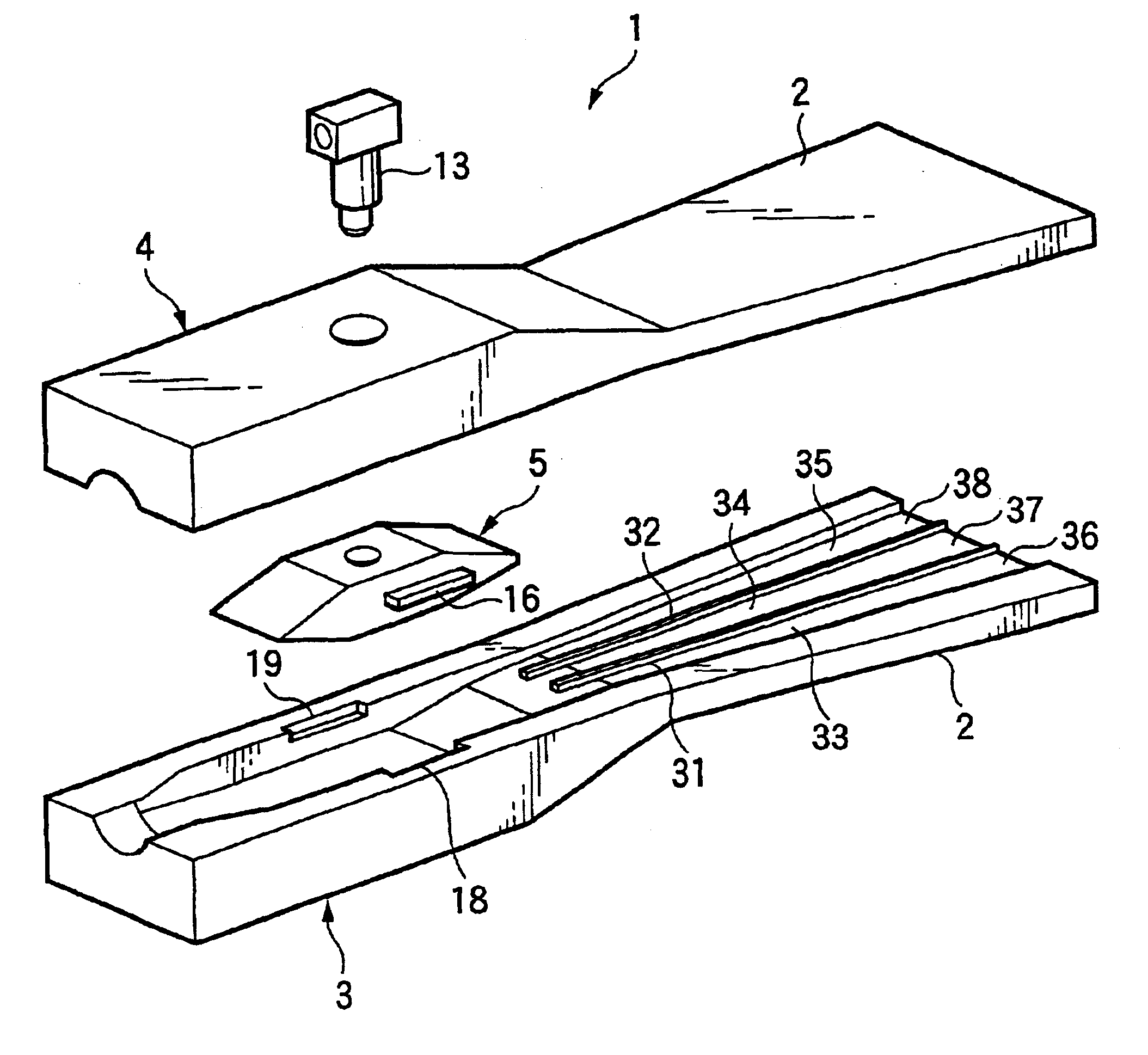
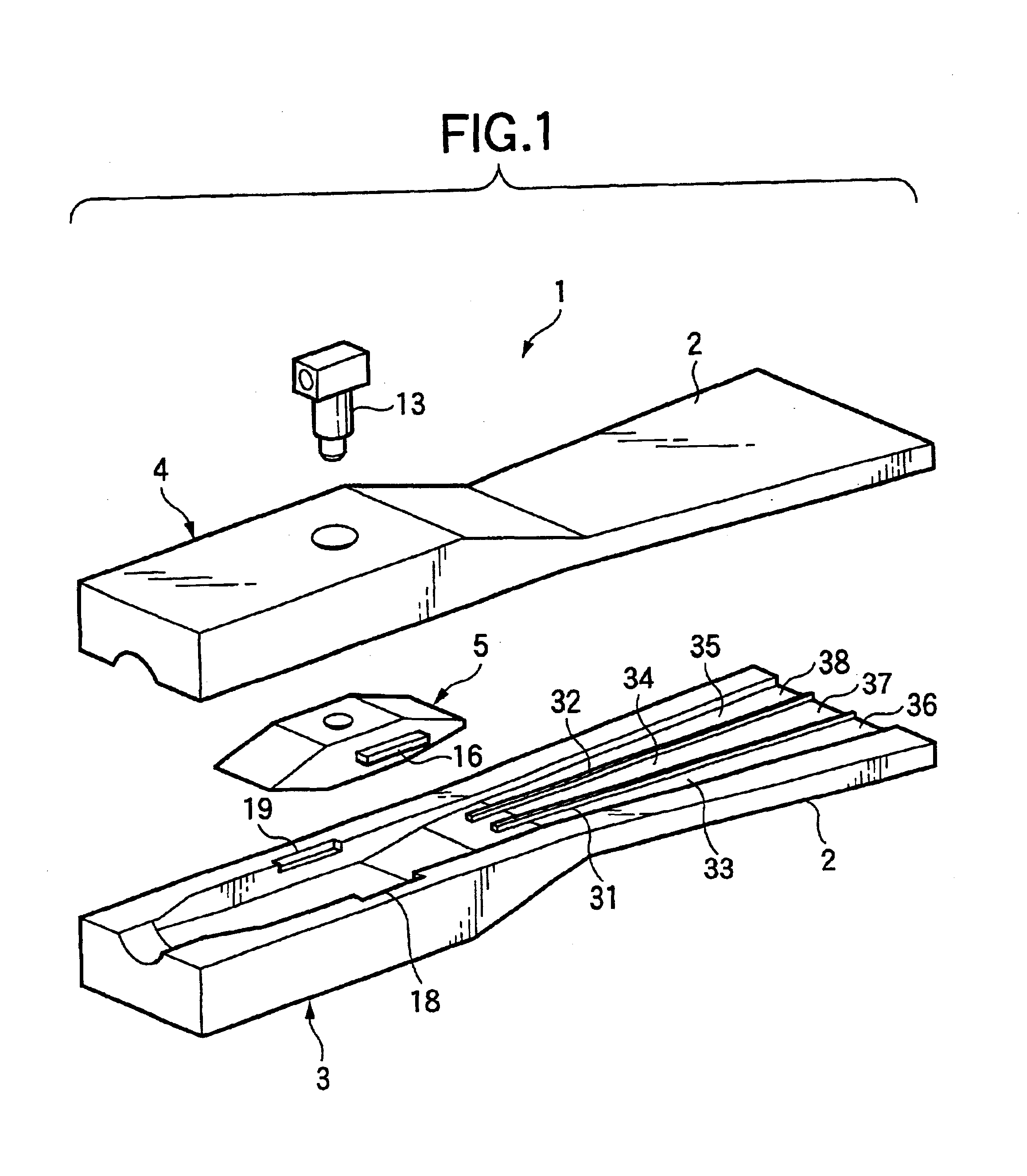
In order to solve the above described problems, in a jetting apparatus according to the invention for a mixed flow of gas and liquid which is so constructed as to mix at least liquid and gas to create the mixed flow of the gas and the liquid and jet it, the jetting apparatus comprising: a passage of the mixed flow of the gas and the liquid, said passage including at least one partition and a plurality of sub-passages divided by said partition; and
liquid injection ports being provided in correspondence with said divided sub-passages; wherein
mass flow per sectional area of the mixed flow of the gas and the liquid passing through said respective sub-passages is substantially equal. In the present invention, the passage of the mixed flow of the gas and the liquid is formed flat, and an inside of the passage is divided by the partitions into a plurality of streams (sub-passages) to supply the liquid from the
liquid injection ports corresponding to the respective sub-passages. Accordingly, the streams of the mixed flow of the gas and the liquid in the respective sub-passages can be properly created as predetermined. In other words, considering number of the liquid injection ports to be provided, injection conditions, positional relation between the positions of the liquid injection ports and the aforesaid partitions and so on, the
mass flow per sectional area of the streams of the mixed flow of the gas and the liquid in the respective sub-passages can be made substantially equal. It is thus possible to easily obtain a flat mixed flow of the gas and the liquid having less blowing variations, favorable in uniformity, and having a wide blowing range.
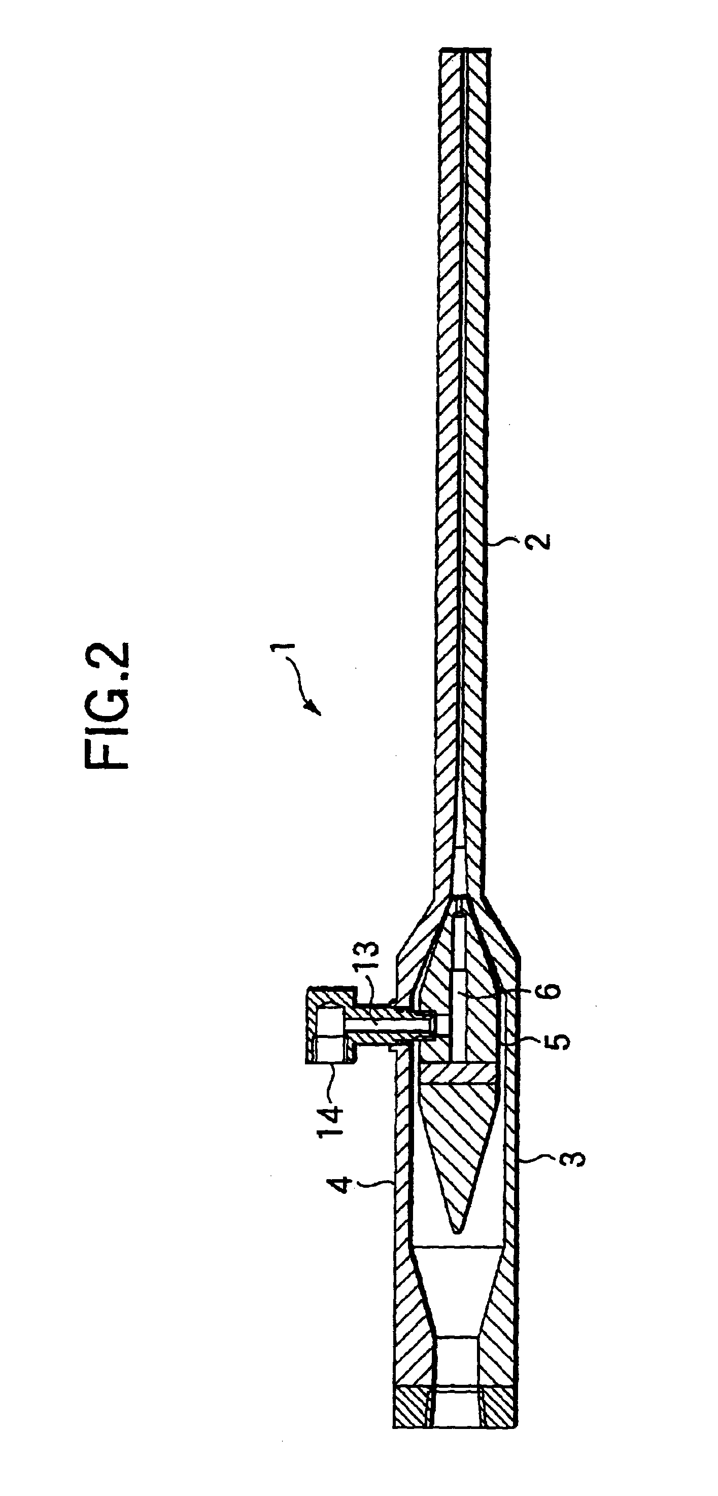
Moreover, each of the divided sub-passages may be gradually increased in a downstream direction in width in a direction in which the sub-passages are arranged. Also, each of the divided sub-passages may be gradually increased in a downstream direction in width in a direction perpendicular to a direction in which the sub-passages are arranged. Further, terminal ends of the partitions maybe located at an intermediate position in the passage of the mixed flow of the gas and the liquid. Still further, upstream ends of the partitions can be located at an appropriate distance from the liquid injection ports. Still further, by gradually decreasing sectional area of a gas passage for supplying the gas to the passage of the mixed flow of the gas and the liquid toward a supply port of the gas to increase
injection rate of the gas, deceleration of the liquid injected from the aforesaid
injection port can be restrained. Still further, by providing the passage of the mixed flow of the gas and the liquid with a minimum
throttle portion which has the smallest sectional area, and making sectional area in the downstream part thereof equal to that of the minimum
throttle portion or gradually increased, it is possible to restrain deceleration of the mixed flow of the gas and the liquid or accelerate it in the respective passages.
Further, the partitions need not always be provided up to a tip end of the
nozzle portion, but the terminal ends of the partitions may be located at an intermediate position in the passage of the mixed flow of the gas and the liquid. With such arrangement, streams of the mixed flow of the gas and the liquid which have been divided by the aforesaid partitions join together at the intermediate position between the terminal ends of the partitions and the injection ports in the downstream part, and boundaries existing between these streams of the mixed flow of the gas and the liquid will be eliminated. Accordingly, a more favorable
jet flow having no boundary can be obtained, and strip-like blowing due to the boundaries between the streams of the mixed flow of the gas and the liquid can be appropriately avoided. In this connection, the terminal ends of the aforesaid partitions may be formed in a step-like shape, an inclined shape or a bifurcated shape, as shown in the embodiments described below. In such cases, sudden merging of the streams of the mixed flow of the gas and the liquid in the respective passages occurring at the terminal ends of the partitions will be moderated, and therefore, more smooth merging of the mixed flow of the gas and the liquid can be attained.

