
Method and apparatus for 3D laser printing by heating/fusing metal wire or powder material with controllable melt pool

a technology of controllable melt pool, which is applied in the field apparatus and a method of 3d laser printing by fusing metal wire or powder material with controllable melt pool, can solve the problems of poorly understood parameters

Pending Publication Date: 2021-09-16
DOGRU JOHN MEHMET ULGAR +1
View PDF6 Cites 3 Cited by
  • Summary
  • Abstract
  • Description
  • Claims
  • Application Information

AI Technical Summary

Benefits of technology

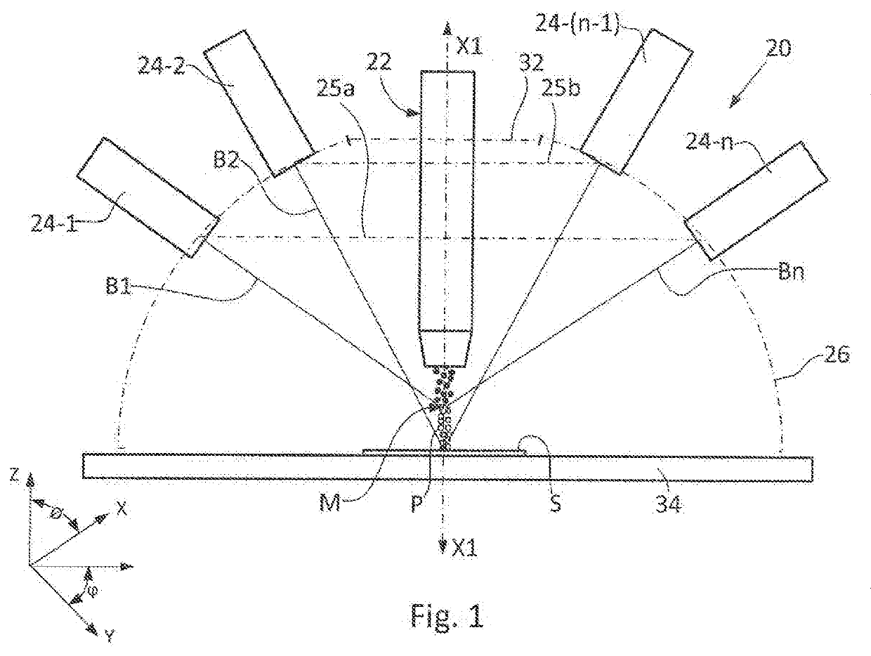
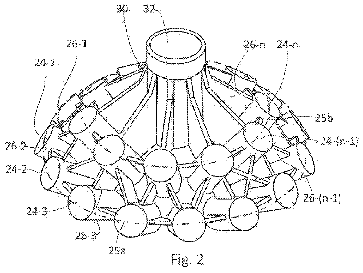
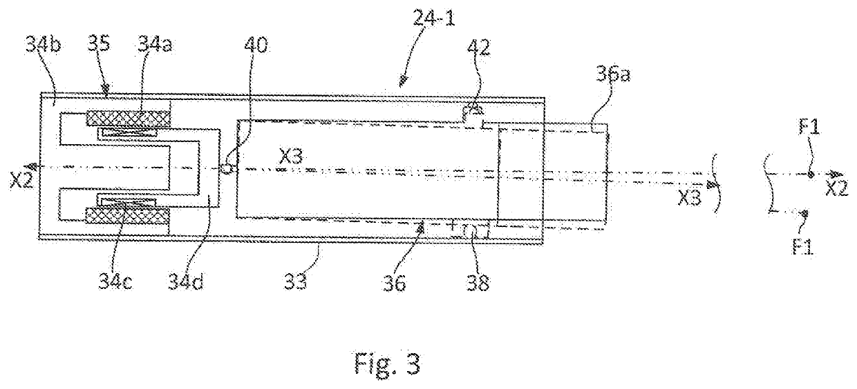
The patent describes an apparatus for 3D laser printing and a method for fusing a metal material with control of a melt pool on a substrate. The apparatus includes a metal wire or powder feed unit and a plurality of identical laser sources symmetrically arranged on the surface of an imaginary hemisphere. Each laser source contains a laser with a laser-beam focusing lens that focuses the laser beam in a focal point at a given distance from the focusing lens. The laser source is also provided with CPU / GPU-controlled devices for independently shifting each laser or a group of lasers along the optical axis and / or for tilting the lasers relative to the longitudinal axis of the laser source housing so that the focal points of the lasers can be selectively positioned at any point of the fed material or on a substrate for forming and controlling the melt pool. This technology can control the position and size of the melt pool, which can improve the precision and quality of the printed objects.

Problems solved by technology

Despite their importance to process modelling, these parameters remain poorly understood due to the high spatial and time resolution required to probe them on length and time scales relevant to melt pool fluctuations.

Method used


Image

  • Method and apparatus for 3D laser printing by heating/fusing metal wire or powder material with controllable melt pool
  • Method and apparatus for 3D laser printing by heating/fusing metal wire or powder material with controllable melt pool
  • Method and apparatus for 3D laser printing by heating/fusing metal wire or powder material with controllable melt pool

Examples


Embodiment Construction

[0023]The present invention relates to laser printing, more particularly to 3D laser printing, and specifically to an apparatus and a method for 3D laser printing by fusing a metal wire material with controllable melt pool. The invention may find use in additive manufacturing for the production of various models having intricate shapes the production of which by conventional manufacturing methods requires the use of a complicated and expensive equipment that involves multiple manufacturing steps, etc. The invention may also find use in creation of souvenir products, design of jewelry and interior items, creation of architectural models, creation of spare parts and technical structures, creation of trial packaging designs, and the like.

[0024]The invention will be described below in more detail with reference to specific drawings that illustrate modifications according to various aspects of the invention.

[0025]As shown in FIG. 1, which is a schematic general sectional view of an appar...


PUM

PropertyMeasurementUnit
focal lengthsaaaaaaaaaa
degrees of freedomaaaaaaaaaa

Abstract

An apparatus for 3D laser printing and a method for fusing a metal material with control of a melt pool on a substrate are provided. The apparatus contains a metal wire or powder feed unit and a plurality of laser sources symmetrically arranged on the surface of an imaginary hemisphere. Each laser source contains a laser with a laser beam focusing lens that focuses the laser beam in a focal point at a given distance from the focusing lens. The laser source is also provided with CPU / GPU-controlled devices for independently shifting each laser or a group of lasers along the optical axis and / or for tilting the lasers relative to the longitudinal axis of the source housing so that heating or fusing can be performed by placing the focal points of the lasers selectively at any point of the material or on a substrate for forming and controlling the melt pool.

Description

FIELD OF THE INVENTION[0001]The present invention relates to laser printing, more particularly to 3D laser printing, and specifically to an apparatus and a method for 3D laser printing by fusing a metal wire or powder material with controllable melt pool. The invention may find use in additive manufacturing for the production of various models having intricate shapes the production of which by conventional manufacturing methods requires the use of a complicated and expensive equipment that involves multiple manufacturing steps, etc. The invention may also find use in creation of souvenir products, design of jewelry and interior items, creation of architectural models, creation of spare parts and technical structures, creation of trial packaging designs, and the like.DESCRIPTION OF THE PRIOR ART[0002]In spite of the fact that 3D laser printing is a rather recent technology, nowadays there exist already a great variety of various apparatuses and methods for employing this technology i...

Claims


Application Information

Patent Timeline
Patent Type & Authority Applications(United States)
IPC IPC(8): B23K26/354B23K26/035B23K26/06B23K26/342B23K26/08B33Y30/00B33Y10/00
CPCB23K26/354B23K26/035B23K26/0648B33Y10/00B23K26/0876B33Y30/00B23K26/342B23K26/0604B23K26/144Y02P10/25B22F12/45B22F10/368B33Y50/02B23K26/147B22F10/25B22F2999/00B22F12/22B22F12/30
Inventor DOGRU, JOHN MEHMET ULGARVEDESHIN, ANTON
Owner DOGRU JOHN MEHMET ULGAR
Learn More