Pool gutter and air exhaust assembly

Active Publication Date: 2021-09-16
PADDOCK POOL EQUIP
27 Cites 1 Cited by

AI-Extracted Technical Summary

Problems solved by technology

The chemicals used to treat water in a swimming pool create contaminants that may be harmful to swimmers and others present within an enclosure housing a swimming pool (i.e., natatorium).
The contaminants (e.g., chloramine) can irritate the eyes and air passages of individuals in and around the pool area.
Unfortunately, greater amounts...

Method used

[0020]FIG. 5 is a cross-sectional view of the surge tank (25). Combined water-air line (24) extends into the surge tank. An optional Tee fitting (45) is preferably provided to facilitate directing water downwardly into the tank, and contaminate laden air upwardly as shown. A water line (not shown) is provided to draw water from the surge tank through the filter, pump and other components of the water filtration system (30). An automatic water level controller (52) is preferably located within surge tank (25) to control the water level between a minimum level (53) that is above the lower opening (48) of the Tee fitting and a predetermined maximum water level (54). An exhaust stack (47) is provided in an upper portion of the surge tank that is connected to an exhaust fan or blower (49), which is preferably located exterior to the natatorium housing the swimming pool, and which may emit the contaminated air to the ambient or direct it for treatment. The exhaust fan operates to generate below atmospheric pressure within the interior of the surge tank and within the exhaust air plenum (38) of the combination water and air exhaust gutter assembly (33). The partition (37) within the gutter assembly (33) functions to partially seal the exhaust air plenum (38...

Abstract

A pool perimeter assembly extending along a portion of a pool perimeter includes a combined gutter assembly having a gutter conduit and a grate supported above the gutter conduit. The combined gutter assembly also has a partition dividing the gutter conduit to form an exhaust air plenum on one side of the partition. A surge tank is fluidly connected to through a modified converter box and a water-air line to the exhaust air plenum. An exhaust fan is connected to the surge tank and generates below atmospheric pressure so that the contaminated air on the pool surface is drawn through the grate and into the exhaust air plenum, through the water-air line, into the surge tank, and of the surge tank through the exhaust fan.

Application Domain

GymnasiumSwimming pools

Technology Topic

ConvertersWater pool +4

Image

  • Pool gutter and air exhaust assembly
  • Pool gutter and air exhaust assembly
  • Pool gutter and air exhaust assembly

Examples

  • Experimental program(1)

Example

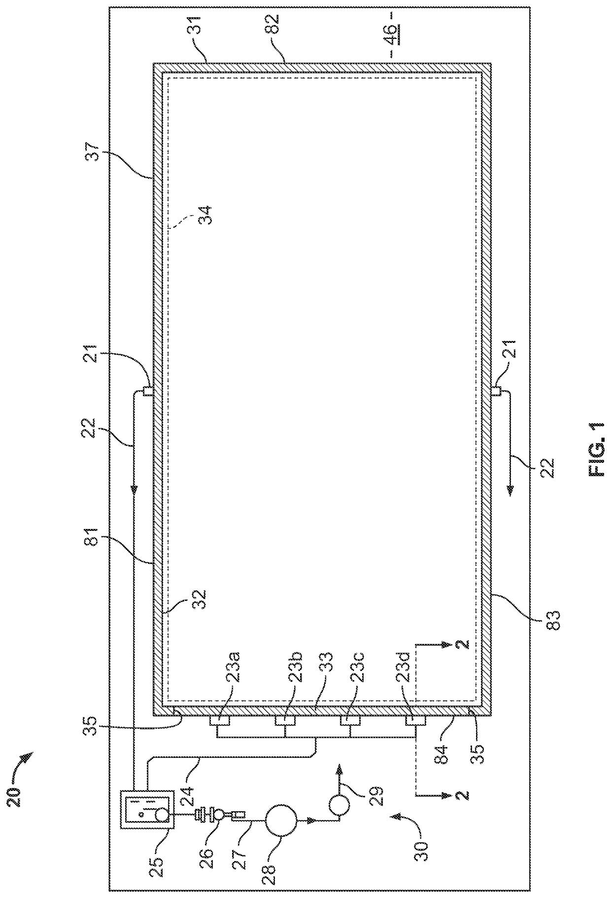
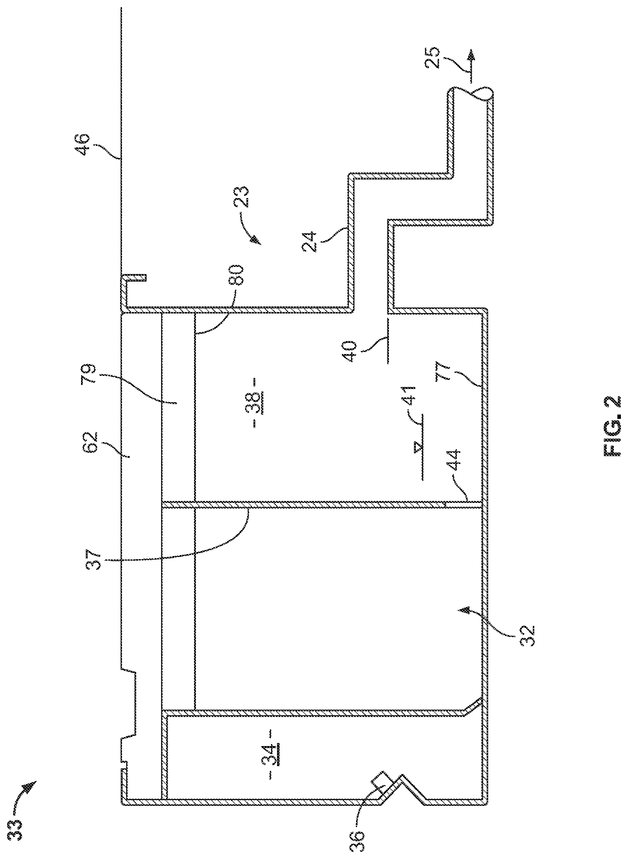
[0015]Turning now to the drawings, an embodiment of a pool perimeter assembly (20) is shown in FIG. 1. Three of four sides (81, 82, 83) of a pool perimeter comprise a conventional gutter system (31) for receiving and draining back-splash pool water. A preferred embodiment of the perimeter gutter system comprises a gutter conduit (32) and a filtered water return conduit, indicated schematically at (34) in FIG. 1. The filtered water return conduit may extend around the entire perimeter of the pool as illustrated in FIG. 1. However, in other embodiments the filtered water return conduit extends only partially around the pool perimeter. A plurality of converter boxes (21) collect water from the gutter conduit and convey the same (arrow (22)) to a water filtering and return system, indicated generally at (30). The water filtering and return system comprises a surge tank (25), a strainer (26), a pump, filter (28), and filtered water return line (29) that conveys the filtered water to the filtered water return conduit (34). The particular components, design and configuration of the water filtering and return system (30) may vary to meet regulatory requirements for clean liquids/water in the pool, as is known in the art.
[0016]FIG. 1 further illustrates that a fourth side (84) of the pool perimeter comprises a combined gutter and contaminate laden air exhaust assembly (33). At least one, preferably several modified converter boxes (23a-d) are provided to collect water and exhaust contaminate laden air, as described in greater detail below. The modified converter boxes are connected by combined water-air lines (24) to surge tank (25). Bulkheads (35) close the ends of the combined gutter assembly and separate the combined gutter assembly (33) from the gutter assembly (32).
[0017]Turning now to FIG. 2, the combined gutter assembly (33) comprises a filtered water return conduit (34) and a gutter conduit (32) into which backsplash from the pool enters through a grate (62). The filtered water return conduit (34) is preferred, but not essential to this disclosure. The filtered water return conduit (34) includes spaced water return nozzles (36). The grate (62) is supported on the assembly (33) by a support structure (79) that includes a downwardly projecting flange (80). The gutter conduit (32) is partially divided by a partition (37) to define contaminate laden air exhaust plenum (38). The modified converter box (23) comprises a combined water drain and air exhaust line (24) that conveys water and contaminated air to the surge tank (25). Turbulent flow of water in the water-air line causes entrained chloramine to be released and exhausted. Further, water-air line (24) is oversized without traps to allow for unrestricted air flow. The invert (40) of the water-air line (24) is spaced above a base (77) of the gutter conduit so as to maintain a normal operating level (41) of water in the combined water and air exhaust gutter (33).
[0018]Partition (37) as shown in FIGS. 2 and 3 comprises a plurality of spaced notches (42) in an upper portion of the partition and a plurality of spaced feet (43) on the lower portion of the partition. The notches (42) in the upper portion of the partition are configured to receive and engage flanges (80) of the grate support members. The partition can be secured in the gutter conduit by attaching feet (43) to the base (77) of the gutter conduit by tack welding, for example. Openings (44) are defined between the partition feet (43) to permit water to flow between compartments. The assembly is configured such that the partition extends upwardly proximate to the bottom of grate (62) and the normal operating water level (41) in the gutter conduit is above the top of partition openings (44). Thereby, the partition (37) partially seals off air plenum (38).
[0019]Turning now to FIG. 4, a longitudinal centerline (63) of grate (62) represents the position of the partition (37) beneath the grate (62). Preferably, few if any drain ports are located along the centerline so as to limit the amount of air passing between the bottom of the grate and top of the partition. Transverse centerline (64) represents the position of a modified converter box (23). The pool side of the grate includes multiple drain ports (65) for receiving back-splash water from the pool and deck, and draining the same into the gutter conduit (32). The deck (46) side of the grate includes a second pattern of air exhaust ports (66a-c). The cross-sectional area of the exhaust ports (66a) that are closer to the modified converter box are comparatively small, and increase in cross-sectional area (66b and 66c) with distance from the modified converter box, as shown schematically in FIG. 4. The number, shape and size of the exhaust ports are configured such that the draw of contaminate laden air from above grate (62) is substantially uniform across the longitudinal length of the combined water and air exhaust gutter (33), as is well known in the art. In addition to receiving contaminate laden air, exhaust ports 66 may receive some back-splash water from the pool.
[0020]FIG. 5 is a cross-sectional view of the surge tank (25). Combined water-air line (24) extends into the surge tank. An optional Tee fitting (45) is preferably provided to facilitate directing water downwardly into the tank, and contaminate laden air upwardly as shown. A water line (not shown) is provided to draw water from the surge tank through the filter, pump and other components of the water filtration system (30). An automatic water level controller (52) is preferably located within surge tank (25) to control the water level between a minimum level (53) that is above the lower opening (48) of the Tee fitting and a predetermined maximum water level (54). An exhaust stack (47) is provided in an upper portion of the surge tank that is connected to an exhaust fan or blower (49), which is preferably located exterior to the natatorium housing the swimming pool, and which may emit the contaminated air to the ambient or direct it for treatment. The exhaust fan operates to generate below atmospheric pressure within the interior of the surge tank and within the exhaust air plenum (38) of the combination water and air exhaust gutter assembly (33). The partition (37) within the gutter assembly (33) functions to partially seal the exhaust air plenum (38). The number, size and cross-sectional area of the exhaust ports (66) in the grate, the configuration and size of water-air line (24), and the capacity of exhaust fan (49) are sized and configured to maximize the effectiveness of the intake and exhaust of contaminant laden air. Furthermore, the natatorium HVAC systems is preferably configured to push air across the surface of the pool into the combined water and air exhaust gutter assembly (33) and into the air exhaust system.
[0021]In the embodiment shown in the drawings and described above, the combined water and air exhaust gutter (33) and modified converter boxes (23) are located at one end of the swimming pool. In other embodiments this assembly can be located at other places along the pool perimeter and with shorter or longer lengths. The assembly of the disclosure may extend around the entire perimeter of the pool if desired.
[0022]Further embodiments of the disclosure may comprise converting existing steel or concrete gutter systems to provide contaminant laden air exhaust functionality. Specifically, partitions (37) and bulkheads (35) can be installed in a portion of a previously existing gutter to form a combined water and exhaust air gutter assembly (33) in accordance with the disclosure. The invert of an existing converter box can be raised, or alternatively, one or more modified converter boxes (23) can be provided. Depending on the installation, the existing surge tank may require modification, including the provision of a stack and exhaust fan (49). Preferably a new grate (62) is provided to optimize air flow and to maximize exhaust of contaminant laden air in accordance with the disclosure.
[0023]While a preferred embodiment of the pool gutter and air exhaust assembly has been herein illustrated and described, it is to be appreciated the various changes, rearrangements and modifications may be made therein without departing from the scope of the disclosure.

PUM

no PUM

Description & Claims & Application Information

We can also present the details of the Description, Claims and Application information to help users get a comprehensive understanding of the technical details of the patent, such as background art, summary of invention, brief description of drawings, description of embodiments, and other original content. On the other hand, users can also determine the specific scope of protection of the technology through the list of claims; as well as understand the changes in the life cycle of the technology with the presentation of the patent timeline. Login to view more.
Why Eureka
Try Eureka